
My Builds – B.A.D 1
Written by
Brief Summary
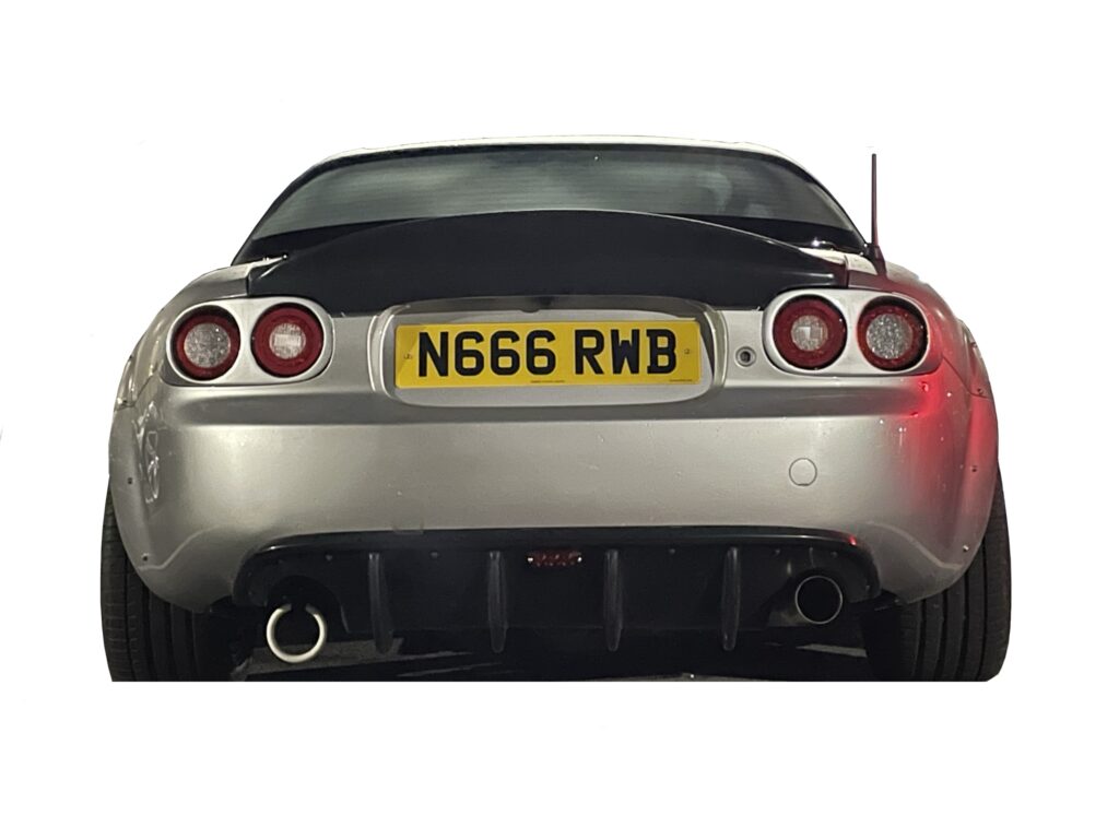
The vehicle known as “B.A.D 1” in my ever growing fleet is the very first of it’s kind. Who’d of guessed by its designation lol. It started life out as a 2006 Mazda MX-5, commonly known as a NC1 chassis. She’s the second vehicle I own since passing my driving test. She is my first attempt at a widebody high level grip car. Built with the intention to train myself to become a better driver.
Detailed Summary
Physically B.A.D 1 is just a basic MX-5 NC1 chassis with the factory soft-top roof mechanism removed. A 5Race roll-bar and door-bars fitted. With the stock 2.0litre LF-VE engine turbocharged with a Garrett unit. Running wider Enkei wheels and Michelin tyres. Equipped with BC Racing BR-series coilovers for a firm ride. Equipped with Haltech engine management.
Digging a little deeper than just scratching the surface. You want to know the specifics right? I’m about full transparency so you should be able to hypothetically build B.A.D 1 with my following detailed recipe.

Chassis Setup
B.A.D 1 is based off a 2006 Mazda MX-5 NC1 2.0 soft-top chassis. The factory style-bar/rollbar has been totally removed along with the soft-top roof mechanism/structure. This has significant weight saving advantages, with few downsides. The main one being converting a cabriolet into a coupe. However you’d think the car would be louder on the inside and worse vibrations (NVH). But with the factory soft-top removed and the Mazda optional fiberglass hard-top installed the car has a more peaceful interior. To increase safety a proper 5Race rollbar and door-bars have been fitted. A full roll-cage wasn’t deemed appropriate for a mainly fast street car where comfort still remains a consideration. Compared to a thoroughbred racecar.
Suspension Tuning
The suspension setup is actually incredibly simple. I’m using BC-Racing BR-series coilovers that originally came with straight 6KG front and 4KG rear springs. Back when I used to run a rather weak spec 17x8J 235/40/17 setup, the spring-rates were ideal. However with a slightly heavier wheel and tyre combination of 17x10J and 255/40/17 I listened to Brain from Goodwin-Racing’s advice on the spring-rates for the wheel and tyre combo. So following that advice for a mostly fast street car and weekend track car I went with the least aggressive option. That being straight 10KG front and and 7KG rear.

Wheels and Tyres
Possibly the most controversial part of this car, beside my unhealthy obsession with over-engineering all my modifications. Is the wider 17″ wheels. They are in fact 17x10J ET38 Enkei RPF1’s. Meaning they are a 17″ wide wheel with a 10″ inch barrel (width of the alloy wheel) with a +ET38 offset. Wrapped in Michelin PS4 255/40/17″ square setup.
How does that compare to the stock 17″ sport wheels? Well from memory the stock wheels are +ET55 17x7J wrapped in 205/45/17 tyres. So when we compare the alloy wheels are 3″ wider per side. The tyres are 50mm wider per side. The track width is considerably wider. Meaning we have 6″ wider wheels overall before tyres and then the actual tyres making the contact patch are 100mm wider overall. I know for certain not the widest setup on a NC chassis however. Wide for 17″ wheel limitations. 17″ is the ideal width face, compared to 16″ and 18″ offerings. 18″ opens wider more available tyre sizes. But requires a rubber band like sidewall. Which increases the chance of a pot-hole cracking an alloy wheel, given I am based in Wiltshire the county with the worst pot-holes in the country I cannot and would never run skinny tyres. I much prefer a chunky sidewall regardless of road conditions. Some people run staggered setups, meaning the front and rear axles are different spec wheels and tyres. I originally wanted 275mm or 305mm tyres for the rear axle. Upon discovering the just mentioned limitations in the tyre size offerings it made sense to use the same size as the front axle for the rear. Yes it’s harder to steer at slower speed but it’s so worth it. The grip in the front and rear is insane. I personally believe it’s the ideal balance for my end power goal.
The tyres being Michelin PS4’s were just a solid choice as a high performance summer tyre. I had debated semi-slicks but felt the PS4’s would suit it for the time being. It does rain here a hell of a lot in England so it meant I can enjoy the car in the wet. Vs a mid-tier semi-slick tyre in the wet.
Powertrain Details
So here comes the sauce. The engine. The factory 2.0litre LF-VE found in the early NC1 chassis is incredibly underwhelming at 160BHP & 190Nm. Let’s not even speak of the awful 1.8litre L8-VE engine. So to put things right and liven the chassis up. I turned to forced induction. Being an avid fan of gas-turbine engines it’s pretty easy to know why I went with a turbocharger if you understand both piston and gas-turbine engine history. There’s nothing better than using waste energy in the form of thermal energy to create even more power versus the older conventional crankshaft-driven supercharger method. So let’s dig deeper.
Turbo Manifold
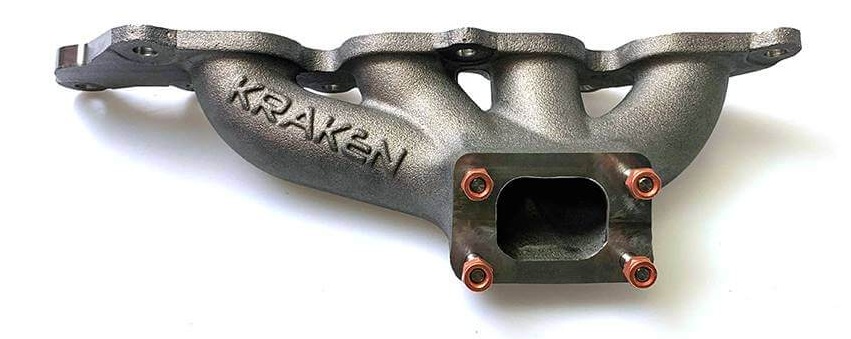
In order to even fit my Garrett turbocharger I first needed an turbo-manifold to connect the exhaust ports into one single T25 flange port to feed my large small-frame turbo. That’s where Kraken.EU came in. I use their cast T25 manifold that fits both the 2.0litre LF-VE and the 2.5 Duratech Ford derivative. It doesn’t come without drawbacks which I’ll get onto later. But the main reason I chose this manifold was its cast-iron. Compared to a tubular welded 316 stainless-steel manifold. Which in this instance means it’s more compact and more reliable in terms of heat-cycling. As for any turbocharger to make significant power the turbo itself must be as close to the exhaust ports as possible to make use of that wasted thermal energy going out the exhaust. The closer the turbo sits the higher the EGT (Exhaust Gas Temperature) and with some very rudimentary physics that means the higher the gas velocity (Speed) . In turn be able to do more work with that otherwise wasted thermal energy. One of the carveouts being primary runner length. The Kraken.EU manifold has unequal primary runners. Which does mean the manifolds characteristics are not as efficient as a tubular welded manifold with equal length primary runners. Without going into too much science it’s to do with the exhaust pulses as the engine fires. Equal length runners are generally speaking always more efficient than unequal.
Turbo
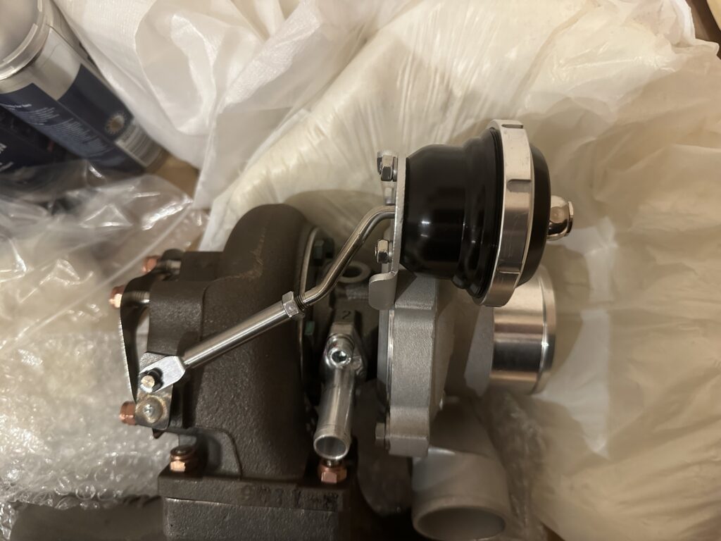
The turbocharger itself is a Garrett unit for one main reason compared to other more affordable manufacturers. Many people probably don’t know this but Garrett is a Honeywell company. Actually develop gas-turbine engines for aviation. So out of all the turbocharger manufactures they are the most knowledgeable. That and I got a very good deal on a unit from Michael at Kraken.EU. The model turbocharger is a GT2871R 0.64A/R. It’s a large small-frame turbo. Ideal for 2000cc of exhaust gas flow. It is indeed an older model turbo when compared to their newer faster spooling G25 series range. However while a smaller turbo like a TD04 or TD05 found in many Subaru’s might spool sooner. That is not necessarily a great thing for a naturally aspirated engine that was never equipped to be turbocharged. Why? Even with uprated internals the engines blueprint or design is still fundamentally the same dimensions. So the problem with that is if you make a lot of boost down in the low-mid powerband (RPM range) then that means peak torque will be down in those low RPM’s. Not ideal. This is because you have to understand both RPM which is the rotating speed of the crankshaft and reciprocating speed (piston speed). They are not the same. With low RPM and peak torque the piston speed is a lot less than at mid-high RPM. Which in turn puts more stress on the connecting-rods and piston assemblies per stroke vs when the crankshaft (RPM) is faster there stress is more evened out. That is a crude explanation but should convey the problem and solution.
Downpipe
The downpipe has been fabricated by my mate Rich at RichFabrication in Oxford. All 316 stainless steel construction using manufactured bends. This is something that Rich pointed out to me which I never realised. He chooses to use manufactured bends because when you bend exhaust pipe with an air-over-hydraulic bender you can, depending on the angle drastically stretch and ultimately thin the bend area. Resulting in even thinner than ideal wall thickness. Whereas a manufactured bend is the same thickness throughout. Worth mentioning in terms of strength. I’d highly suggest Rich if you’re in the market for a custom stainless steel exhaust, he specialises in exhaust but he also does other fabrication work. A handy bloke to know.
This downpipe is probably one of the most awkward downpipes Rich has ever fabricated. The lack of space from the back of the turbine exhaust flange and the shape of the engine bay made it one hell of a challenge. It goes from the T25 flange to a compact 90 degree piece with 3″ inch v-band. So installation of this piece is possible having to deal with the irritating 5 stud affair. The other side of the 3″ inch V-band goes directly into the 45 angled Magnaflow 200cell catalyst. I opted for a 200cell catalyst because I’m not a fan of the smell of a decatted vehicle during a cold-start. That rich smell of lovely hydrocarbons is not my thing lol. Many people try and spread false information about high flow catalysts. In reality theres been many real world dyno tests and the horsepower and torque with and without a high flow catalyst like the common 200cell results in negligible power loss. I will briefly mention that the factory Mazda primary catalyst is 400cell. For comparison, the cell count is per inch cross-section. Meaning the larger the value the more restriction to flow. That’s where the misinformation comes along, a 400cell factory catalyst will restrict power. Whereas a 200cell or even higher flowing not as common 100cell catalyst will not create significant restriction to cause measurable power losses.
Engine Management
As for engine management. I think most people are already aware as I speak highly of them but I use Haltech for this job. Haltech make installation and tuning a breeze with such a clean UI. Coming from someone whose never configured a full standalone ECU before it honestly could not be easier. I personally use the older Elite series as that was the standard at the time I purchased my ECU and patch-loom. The Elite 1500 to be exact. Still by all means a very capable ECU and Haltech a couple years ago released new firmware to allow the Elite series of ECU’s to work with the more modern tuning suite NSP (Nexus Series Programmer) which is the very latest series of ECU’s. To make the Haltech Elite 1500 plug and play for the most part, I use a patch-harness from Chris over at RoadsterWireWorks.
On my revision of the harness I did opt into changing the alternator rectifier board to change it to a self-regulating unit which he provided. Which meant a more stable charge voltage versus loosing more I/O for alternator field control within the Elite 1500. You can opt out of that and let the Haltech control it but you loose spare I/O in the auxiliary connector he leaves which is a Deustch DTM 12pin. To modify the alternator it is just the case of impacting the pully and nut off the front drive. Then splitting the cases and swapping the PCB out for a similar unit. Then reassemble. If you do it I strongly suggest you complete it within the same day just so your brain can’t forget the order of the components within.
Wideband WB1
The Haltech network does not just stop with the ECU. I have many Haltech CAN devices. The first being the NTK WB1 Single-channel controller & sensor combo. This is required by the ECU in order to do short-term and long-term fuel trims and ultimately make use of the Elite 1500’s three-stage engine protection strategies. I opted for the NTK sensor variant over the widely popular Bosch LSU4.9 variant. Main reasons are the sensor has a wider AFR range than the LSU4.9 sensor. The sensor is also more resilient to being in a harsh motorsport environment. The difference between single and dual channel controllers relies on the engine configuration you have. For instance an engine with multiple banks (such as a V8) will require at minimum a sensor per bank. That would be after the collector on both exhaust manifolds or to the aft of the twin turbos. However some single bank engines are an exception to this rule such as the Toyota 2JZ which has two exhaust manifolds with two o2/lambda sensors per manifold aft the collector. However on most conventional four cylinder engines a single oxygen sensor is enough. On a stock vehicle with a catalyst there will be a primary and secondary. If you’re running any standalone ECU you only require the primary oxygen sensor. The secondary is simple for emissions and verifying the catalyst(s) are working in factory form. I will briefly touch on what a o2/lambda/oxygen sensor does. It should come to no shock that the sensor is indeed as the name says monitoring the presence of oxygen in the exhaust. Why? Because then it can calculate the Air:Fuel ratio upstream inside the combustion chamber. Which is absolutely VITAL on a four-stroke spark-ignition engine.
CAN Gauge
Continuing on with the other CAN devices I have, I use the Haltech x ScanArt 52mm digital CAN gauge to display additional information that the factory instrument cluster never had available. Such as engine oil pressure, engine oil temperature, engine coolant pressure, fuel pressure, fuel temperature and many more should I need. All transmitted to the gauge via Haltech CANBUS protocol. Which is plug and play, more on that later. The a-pillar pod was custom made by a close mate who is an upholstery wizard. Both a-pillars are wrapped in black suede to help reduce glare. and aesthetics.
CAN Keypad
One of my favourite CAN devices in my car is the CAN keypad. This variant is the 2×4 model so eight total keys. I’m only scratching the surface when I say this a game changer. Why? Having the ability to change strategies within the ECU at moments notice with a single button press while driving is awesome stuff. I use mine for cruise-control, traction-control strategies, launch-control strategies, boost-control strategies and more. Essentially when you map the buttons in the NSP suite you have four button states (OFF/1/2/3). So I have TC OFF, STRONG, MID, LOW levels of traction-control by hacking the button. When that’s used in a 3D table, that can change the third axis and cycle between three different tables.
I/O Expander Box
Finally the last CAN device I have which was added after initial installation of the ECU and WB1 controller is the older Haltech I/O Expander Box. This unit looks like the platinum series ECU’s that Haltech used to manufacture. As the name suggests this unit provides even more I/O (Inputs & Outputs) such as DPO’s and AVI’s. (Digital Pulse Output – Essentially a switched ground connection for duty cycle devices such as boost-controllers) (Analogue Voltage Inputs – 0-5Volt and/or 0-12Volt inputs). The Elite 1500 only has a limited amount of I/O available out of the box. However with the CAN I/O Expander Box I have more I/O available for additional sensors, switches and solenoids.
CAN Hub
I did mention that these devices were all plug and play. Here’s how. Each CAN device from Haltech will come with a 4pin Deutsch DTM male plug on the end. In order to connect numerous devices into the Elite 1500 I use the front CAN port under the cover for the Haltech CANBUS. The CANBUS pins out of the main ECU connectors are used for the Mazda CANBUS for communicating with devices such as the ABS module. Which will transmit individual wheel speed data into the ECU. As the wheel-speed sensors are wired to the ABS module not the ECU. But the way I go from that single port on the ECU itself to my devices is the Haltech 4port CAN hub. Now for those that are switched on, will realise that this leaves three ports for devices not four. You’d be bang on the money. The WB1 NTK single-channel controller has a pass-through for another CAN device. So the CAN keypad is connect through the WB1.
Aux Harness
In addition to the I/O Expander Box harness I have also manufactured my own custom harness that goes into that 12pin Deutsch DTM plug that I mentioned much further above. That is how I added the engine oil-pressure sensor, engine oil-temperature sensor, fuel-pressure and temperature combi sensor. Chris does not include these in the RoadsterWireWorks patch-loom because the factory engine never had these and placement would be custom depending on your setup. So that is a job for yourself. I will briefly mention if you have a Haltech Elite 1500 or greater ECU and you’re not running a fuel-pressure sensor then you’re doing yourself a disservice. Not only do you not take advantage of the three-stage engine protection. But in a boosted application the way you’ll tune the engine without a fuel-pressure sensor is estimating, not relying on a true value. I’ll explain that later when it comes to the fuel system. The same can be said about the ever so important engine oil-pressure and engine oil-temperature sensors. The ECU is your friend and will catch a problem and take action faster than you can begin to process what’s even happening. Use it!
Fuel System
Fuel Sender Unit
When it comes to the standard NC fuel system it is very limited from the factory. So for the most part my setup uses all new components to achieve a reliable 500BHP worth of fuel supply. I’ll do my best to condense this section as much as possible as there’s a lot of components. I’ll start from the fuel tank. The fuel pump has been replaced by a Deutschworks DW300C 340LPH in-tank submersible pump. The factory in-tank fuel-pressure-regulator (FPR) has been replaced by a FPR delete piece from the famous Armand Hindrich’s. This is done to send full unregulated fuel to the engine compartment. The fuel hat has been replaced by a hat also by Armand. He is the first company that decided to make the NC specific fuel components. The fuel-level-sender has had the submersible connector removed and ring terminals crimped on the tails. Then connected to the new pair of studs for the sensor on Armands new fuel-hat. The fuel pump has also had the same treatment with the submersible connector removed and ring-terminals crimped onto the tails. That covers the wiring in the tank. To connect the pump and ultimately the output from the FPR-delete to the new fuel-hat bulkhead fittings I use J9 submersible in-tank hose. That connects to a male (CHECK)13mm barb to -8AN female. This is for the supply line. The return line is (IDK YET)
Fuel Lines
To get the fuel from the tank to the engine we first start at the top of Armand’s fuel-hat. The supply line uses a -8AN bulkhead 90 degree fitting with the corresponding PTFE/Nylon washers to seal the vapours within the tank. From there I’ve used a straight PTFE -8AN female to -8AN SS hose. The return line uses a -6AN bulkhead 90 degree fitting with the PTFE washers like the -8AN. From there it goes into a -6AN 90 degree PTFE female to -6AN SS hose. Yes you heard that correct, I have indeed run two brand new fuel hoses/lines to the engine compartment that are the PTFE (not rubber kind). Then removed the factory fuel supply-line and EVAP line entirely from the vehicle. The two -8AN and -6AN lines run from the top of the tank down past the tank. Right below where the supply-line goes into a Radium fuel-filter mounted onto the PPF (Power Plant Frame) using large rubber p-clamps. The PPF was drilled and a suitable stainless-steel nut and bolt was used. To connect -8AN supply hose to the filter inlet I used a 120 degree PTFE full-flow female fitting. Then a -8AN ORB to male flare adapter is used both on the inlet and outlet of the filter to connect to a female -8AN fitting. Coming away from the filter I use a straight PTFE female -8AN fitting. The return -6AN hose runs past the filter and is cable tied with the supply -8AN line. The supply-line is actually clipped to the PPF via rubber p-clips in three different locations as the hoses run towards the engine compartment.
Fuel Rail & Regulator
Coming up following the shape of the trans tunnel as it sweeps up into the engine bay. The supply -8AN PTFE line goes into the back of the fuel rail using a 120degree full-flow PTFE -8AN female fitting. That screws onto a -8AN ORB male to -8AN male flare adapter into the aft of fuel rail. As the fuel flows across the Radium fuel rail on one of the side -8AN ORB ports there’s a Radium fuel-pulse-damper screwed into the rail using a ForeInnovations -8AN ORB spacer (in order to clear the intake manifold). Fuel continues to the front of the fuel rail where it goes into a -8AN ORB swivel banjo to -6AN male flare. Then a -6AN 120 degree PTFE female fitting connects to the banjo. The -6AN PTFE (crossover hose) travels towards the Radium DMR (which despite it’s name is not directly mounted to the rail).
I decided to remote mount the regulator as even with the black steel engine-lifting-eye removed from the head. The regulator being very compact by design, the bottom of the regulator where the banjo fitting resides would contact the head. So I decided for NVH and to avoid placing the regulator in the port that the fuel-pulse-damper lives, which is a bad idea having the regulator sit between cyl 1 and cyl 2 injectors. Whereas now the fuel has to travel across all the injectors evenly. A much better way to make a reliable high horsepower fuel system.
Once the -6AN PTFE crossover hose gets to the Radium DMR it goes into a straight PTFE -6AN female fitting thats then screwed onto a -6AN ORB banjo to male flare. That is the inlet to the regulator. Then before the fuel returns to the tank the regulator itself has a mechanical oil-filled fuel-pressure-gauge by Radium connected into one of the side 1/8″ NPT ports using the supplied 90 degree 1/8″ NPT male to female 1/8″ NPT adapter. This situates the gauge facing towards the front of the engine bay. Easily readable for tuning purposes. The other 1/8″ NPT port has a Bosch combi fuel-pressure and temperature sensor installed. So that the Haltech knows the fuel pressure all the time. The temperature is just useful for datalog purposes. Now the fuel exits the DMR via the bottom using again another -6AN ORB banjo to male flare fitting. Then a straight PTFE -6AN female fitting is connected to that lower banjo. This line now runs back down the firewall/bullhead following the trans tunnel alongside the supply -8AN PTFE hose. Completing the fuel circuit on its way back to the tank.
Notice to Installer
The M8 cap-bolts that Radium supply do not utilise the same depth of thread as the factory fuel rail bolts. I spoke to Radium about this and they said the supplied cap-bolts were adequate. It’s not often you’ll hear me disagree with a manufacture like Radium. But I decided that was irresponsible to use those supplied cap-bolts (again the only thing holding the fuel rail down on the engine is these two bolts) therefore I purchase identical bolts with a larger amount of thread. Since they are both partly-threaded the new longer bolts have the thread start at the same length from under the head so no issues there. The bolts you’ll need for this are
The supplied cap-bolts that are the only two critical fasteners that retain the fuel rail under working conditions are 55mm long. With a thread engagement of 8mm. Compared to the factory fuel rail bolts utilising the full depth of the blind threaded holes on the head. I reached out to Radium and they confirmed that was correct. It’s very rare I’ll disagree with a manufacture but this is an instance. Mazda engineers did not make those holes that depth for a laugh. That would of cost them more money, so therefore it was a important decision they are that deep with the corresponding factory fuel rail bolts. For those unaware the minimum depth of thread for a metric fastener is 1x the width of the fastener going into steel. However going into aluminium it is actually 2x the width of the fastener. Therefore I ended up replacing the supplied cap-bolts with A2 stainless (same as Radium supplied) 65mm long cap-bolts. This meant the factory amount of thread engagement was restored. Reiterating considering that these two bolts are mission critical I was absolutely not happy with 8mm of thread engagement with the cap-bolts they supplied. Fuel system are to be taken very seriously and no shortcuts should be taken. So I felt this was the appropriate action and I suggest others with the same MZR/Duratech branded Radium fuel rail to do the exact same to avoid a protentional failure and resulting in a catastrophic fuel fire. Something I would not wish on anyone’s pride and joy.
Fuel Injectors
In order to eventually make my peak power goal of 500BHP. This engine needs a LOT of fuel. Granted I am only running 98RON octane not E85. Meaning I can run smaller injectors. That said the injectors I chose were the InjectorDynamics ID1050X. Which are 1065cc modified Bosch injectors by InjectorDynamics. These are very reliable injectors used in many famous cars with big power. They are plug and play with the existing engine harness. However it’s worth noting here. These injectors cannot use the retention clip that holds them into the rail. Sounds sketchy right? Well no. That clip is only for installation, that’s it. The only thing holding the injectors down under the rail and cylinder pressure is the two fuel rail bolts. This is normal. So don’t worry about the retention clips. Just be very careful upon installation that the injectors are all seated into the fuel rail deep enough and the O-rings are lubricated with oil to avoid pinching them on install. Make sure the other side of the injector is also correctly seated in the bore in the head. Same notes again.
Lubrication Setup
This is going to upset a few companies when I say this but I honestly couldn’t care. Those who know, know who I’m referring to with this. If you turbocharged any modern vehicle that was naturally-aspirated and did not have any components that sit in the exhaust stream from factory then you should be fitting an oil-cooler to help dissipate the heat the turbo puts into the oil. Yes modern turbos are water-cooled but they still but a lot thermal energy into the same oil that is used to lubricate the engine. Not doing so is amateur and unprofessional. You know who you are.
Engine Block
So the best solution I have created relocates the oil-filter away from the engine and places it on the chassis. In order to do this we need to delete the notoriously weak cast aluminium oil-filter bracket. Then replace it with a take-off plate that will provide us INLET and OUTLET ports as well as some M10x1.0mm ports for engine oil-pressure sensor and turbo-oil-feed. There’s a few on the market but I use this Mountune plate. In my opinion this is the best take-off-plate because of the port positions and the amount of ports. This simply goes against the true mating surface on the side of the engine where the original bracket and gasket would live. Instead it uses two independent o-rings to seal. A far better solution. I recommend using a bit of red-rubber grease or Vaseline to initially hold them in their seats while you mount the plate and torque it to spec.
Both inlet and outlet ports have -10AN full-flow 120degree PTFE female fittings on the ends of black sleeved -10AN PTFE hose. One M10x1.0mm port has a M10x.1.0mm to -AN4 male flare adapter. Then from there a pre-crimped turbo oil-feed hose from MambaTek screws onto the -AN4 male flare. Then the other end connects to the turbo using a -AN4 to Garrett thread size. (REPLACE LATER WITH SIZE THREAD) My GT2871R 0.64A/R has a built-in regulator for oil flow. (This takes clean filtered oil and sends it into the CHRA). The other M10x1.0mm port goes to another hose that is also pre-crimped. This is a Haltech pressure sensor remote mount kit. It uses a M10x.1.0mm to -4AN male flare to connect to the female end of the -4AN hose. At the other end of the hose I use the supplied in the kit -4AN to 1/8″ NPT female adapter. Which then accepts my (FACT CHECK THIS LATER)
Filter Relocation
The other two -10AN PTFE hoses go into another pair of 120degree -10AN PTFE full-flow female fittings. That then goes into the -10AN male flares on my GREDDY x Trust thermostatic remote oil-filter housing. This is the same remote filter housing many Skyline owners use. Very popular with it having an integral thermostat. So you can oversize your oil-cooler all you want and you won’t run the risk of over-cooling the oil. Especially for daily use. This also saves lots of money on additional fittings and an inline-thermostat. Totally unnecessary.
Oil Cooler
asdasdasd
Cooling System
Radiator
Interior Changes
Bucket Seats
Once you enter the cockpit you’ll immediately see the interior has been changed significantly. Having an interior that works with the driver rather than against is incredibly important to me regardless of the vehicle. The awful leather sport seats have been replaced with Sparco EVO QRT regular (size) mounted via Cybul.EU seat base mounts in a fixed position. Very important when it comes to the seat-belts. Which as you can see have been entirely removed and replaced with six-point harnesses from Sparco. These are the Sparco aluminium racer variant which have incredibly lightweight buckles and are easy to get in and out of fast.
Rollbar & Door-bars
The next obvious thing are the 5Race door-bars and rollbar. I touched upon this earlier but it’s a full bolt-in rollbar and the door-bars bolt onto the new rollbar via existing provisional mounts on the rollbar to accept their own door-bars. The other end of the door-bars are connected to the floor via some thick spreader-plates. These are a massive increase in safety over the stock “rollbar” which is hilariously eneemic compared to any rollbar offering, making it like a style-bar with the previous generations offering no real strength and more for show than actually saving your life. I strongly suggest all NC owners fit a bolt-in rollbar at bare minimum even for road use.
Steering-Wheel
The driver controls have been changed to increase safety and control. I should mention at this point I have no remaining operational airbags in this vehicle. That safety system has been superseded with stronger and motorsport grade means. So this why I’ve replaced the horrible factory Mazda steering wheel with a Personal neo grinta 350mm black leather w/ red stitch wheel. The same brand Ayrton Senna used to rock back in his F1 days. Connecting the steering wheel to the steering column I first go connect to a WorksBell Rapidfx 2 quick release. I can actually get into the car with the wheel still attached but I will say in a race suite this will make it significantly easier. I did have a NRG clone quick release but that later developed play and was not very encouraging so I swapped it for the real deal from Japan. That was not cheap lol. From the quick release we go into the WorksBell short boss for the NC/RX-8 chassis(s). This is the best boss you can get for an NC as it comes with everything to remove the SRS light on the dash and also the connector for the clock-spring to allow the factory horn wiring to work with your new steering wheel horn button. The Personal wheel itself does have a carbon-fibre Volantech switch plate, which connects two momentary buttons into the Haltech management via the curly cord and GX-16 quick-release aviation connector by the steering column surround.
Short-Shifter
The shifter we also briefly spoke about above. It is a G-Racing short shifter which is the best short-shifter for an NC. It is so tight and gives you a positive confirmation of what gear your in at any time. It’s about an inch between 3-4 shift. I highly recommend this shifter and G-Racing, Keith is the man! Just be sure to know what generation transmission you have as the 6spd (the stronger NC gearbox) has two different bushings that at the bottom of the turret on the gearbox. NC1 versus NC2/3. Allegedly NC2/3 gearboxes are stronger but I’ve personally seen any concurrent proof of that. You’d be better off just getting a good condition 6spd Mazda gearbox and cryogenically treating it. Which is a service that places can offer that in a very crude sense realign the atoms in the metallurgy after they have been induction hardened.
The pedalbox has a set of I.L. Motorsport pedal covers on them. Apart from the clutch pedal. That is very much custom. I’ll talk more about this later on in the article.
Car Mats
The little bits such as the floor mats are from DiamondCarMats and have been modified to accept my door-bars. The rear area behind the seats where the soft-top and plastics used to live has been covered with this lovely three way stretch black carpet that’s used commonly in VW camper conversions. The sound system is very basic. After all it’s a car with awful acoustics to begin with being a convertible. I much prefer to cruise to engine noise than loud crystal clear music. For that reason I have gone with a Pioneer SPH130-DAB Apple CarPlay head unit that uses its on-board amplifier to power a pair of JBL Stage 8602 6×8″ 2way coaxial speakers in the bottoms of each door-card. The factory sport Bose system has been entirely removed. Leaving only the wiring to be repurposed. Two speakers in the door-cards in a small two seater sports car are plenty. I barely have the volume above 10 for reference.
Lastly I have a one of two fire extinguishers mounted under the passenger seat using “The Brackateer” universal fire extinguisher bracket. The Haltech components are mostly behind the glovebox with the NTK WB1 single channel controller sitting directly behind where the heated seat buttons would of been on the transmission tunnel. Behind the glovebox behind the end piece of the dash is third fusebox for additional devices I’ve installed such as the WB1 controller. The fusebox is a BlueSea systems 6 way (without ground connections).
Custom Adaptations
Clutch pedal setup
Battery relocation
Engine block and components
- Standard NC1 2.0 block.
- Standard NC1 2.0 crankshaft.
- Standard NC1 2.0 pistons and rods.
- Standard NC1 2.0 valvetrain.
- Standard intake manifold, modified by yours truly to delete EGR and to permantely fix variable plenum length to shortest.
- Standard 65mm throttle-body, the anti-icing coolant circuit still connected.
- NC2 revised dip-stick.
- NGK LTR7IX-11 spark plugs.
- Kraken NC unofficial turbo kit
- K&N RE-0910 air-filter.
- Custom air-intake.
Engine oil system
- Mountune E077-09-101 remote oil take-off plate.
- GReddy 12401114 thermostatic oil-filter housing, mount custom made.
- SETRAB ProLine STD 625 Series 6 Oil Cooler 330mm x 193mm 25 Row.
- K&N HP-2009 oil filter.
Cooling System
- Koyorad hyper-v radiator.
- Standard fan and shroud.
- Rerouted exhaust side coolant hose.
- DaveFab coolant tank.
Power-steering system
- Mishimoto MMTC-TF-1575 power-steering cooler.
- Millers power-steering fluid.
Fuel system
- InjectorDynamic EV14 1050cc fuel-injectors.
- Radium fuel-rail.
- Radium rail-mounted fuel-pressure-regulator.
- Radium rail-mounted fuel-pulse-damper.
- ForeInnovations xAN-ORB extension, for fuel-pulse-damper to clear standard intake manifold.
- DW340 fuel-pump.
Management
- Haltech Elite 1500 ECU.
- Haltech WB1 NTK single-channel.
- Haltech I/O Expander Box-B.
- Haltech ScanART 52mm gauge.
- Haltech four-port CAN hub.
- RoadsterWireWorks patch-harness for NC.
- Modified factory engine and body harness, EGR, Lambda’s, Alternator wire and variable intake delete.
- Custom made auxiliary sensor harness.
- 150PSI TexasInstruments pressure sensor, for engine-oil pressure.
- 150PSI TexasInstruments pressure sensor, for coolant pressure.
- 145PSI Bosch fluid pressure and temperature sensor, for fuel pressure and temperature.
- Haltech oil-temperature sensor 1/8NPT, for engine-oil temperature.
Electrical
- Yausa YBX5053 AGM battery, relocated to boot for balance and space reasons.
- Motamec battery enclosure.
Chassis
- BC-Racing BR-series adjustable coilovers.
- BC-Racing BR-series dampening adjustment extenders, for boot access.
- Nielex brake master-cylinder brace
- Custom made brake master heat-shield.
Braking and Clutch System
- V8Roadsters Wilwood four-pot front BBK.
- Motul RBF660 brake and clutch fluid.
- Hel stainless-steel clutch-hose.
- Nielex clutch pedal assembly gusset weld-on brace.
Exterior
- CarbonMiata over-fenders.
- CarbonMiata quad-led brake-lights.
- Relocated third-brake light LED into diffuser.
- eBay rear diffuser.
- “MiniMiracle” Fiberglass duck tail MK3 soft-top spoiler.
- eBay smoked LED side repeaters sequential.
- GV-style front lip.
- Honda S2000 short stubby aerial.
- Generic blind-spot mirrors.
- Generic mirror rain deflectors.
Interior
- Personal neo-grinta 350mm black leather with red-stitch.
- Volantech custom-specced carbon-fibre button panel.
- WorksBell NC/RX8 short-boss kit.
- WorksBell quick-release gen 2.0.
- JFCustoms black leather with red-stitch shift and handbrake boot.
- Pioneer SPH130DAB Apple-Carplay.
- JBL 8602 6×8 2-way coaxial speakers.
- BOSEctomey.
- Pioneer windshield DAB antenna.
- Pioneer telephone microphone.
- Kenwood reverse-camera.
- 5Race bolt-in rollbar.
- 5Race bolt-in doorbars.
- Broadway 300mm flat clip-over rear view mirror.
- Soft-top delete.
- OEM grade black carpet for soft-top delete.
- Sparco EVO QRT’s (regular size).
- Cybul base seat-mounts.
- Sparco 6 point aluminium racer harness.
- I.L. Motorsport centre-storage module.
- Circuit-Sports handbrake button anodised red.
Wheels and Tyres
- Enkei RPF1 17x10J ET43 5×114.3mm.
- Michelin PS4 255/40/17.
- Mutkei SR48 open-ended wheel nuts.
- Mutkei matching locking nuts.
Nice article.