Haltech ECU install into NC chassis
Written by
But, what was wrong with the stock ECU??
Before we start, we need to clarify a few basic facts. Firstly, the stock ECU can run the stock 1.8/2.0 litre MZR/LF engine when the engine is turbocharged or supercharged. In fact, the leading UK tuner BBR has been tuning NC’s while utilizing the stock ecu. They and many others reflash the ecu with software such as VersaTuner or ECUTek. This works quite well as it goes without saying the stock ecu does not have to come out of the vehicle. Reducing work, thus labour costs.
So, if the stock computer can be remapped and BBR have successfully utilised a remapped stock-ecu for their higher-tier turbo and supercharger packages, then why even look further?
A few important reasons to start with. The stock-ecu cannot be tuned on-the-fly. What does this mean? On-the-fly tuning is, as the name may suggest. Changes made almost immediately. A real world example is: a cell’s value in a table. Which could be your base-fuel-map that can easily be modified to another value and a few seconds later the ecu would automatically apply that change. So the engines behaviour would change almost immediately based on the tuners inputs. Speeding up the tuning-process and thus labour-costs. That is particularly important, and we’ll come back to that later in this article.
The next con of utilising the stock-ecu for your engine-management is that even with remapping software you do not have anywhere near the same level of functionality of an aftermarket-ecu. Let’s imagine you want to connect a boost-control-knob to change boost-pressure values on-the-fly. Now, although a remapped stock-ecu can operate a boost-control-solenoid, it has no means of the driver adjusting the pressure setting. This is because of the limited I/O available. Which, on a turbocharged vehicle. It is ultimately a power setting that would be ideal to operate on-the-fly as the driving conditions change. Especially in a competitive car.
The next and relatively simple issue with the stock-ecu is the vehicle does not actually have an oil-pressure-sensor but, alternatively, an oil-pressure-switch that is mechanically designed so that once the engine reaches a pre-determined minimum pressure level, the ecu would shut-down the engine to potentially save the engine’s lifespan. This is foolish for a handful of reasons. So why did Mazda not use a true oil-pressure-sensor instead of an oil-pressure-switch? Simple, cost. So why is it of great value that an aftermarket-ecu knows the engines in-real-time oil-pressure value? Modern ECU’s such as the Haltech Elite series in particular the Elite 1500 has three-stage-engine-protection. We’ll explore this incredibly powerful feature later. But to conclude this point now. If the user-configured engine-oil-pressure falls below the minimum value set, then the Elite 1500 would immediately shut-down the engine regardless of its running-state. So, the minimum engine-oil-pressure is user definable. Most aftermarket-ecu’s all have at least one-stage-engine-protection in today’s market. Haltech just goes further.
These features are merely a handful of reasons why to opt for the Haltech Elite 1500 for your NC build. I haven’t even scratched the ice on its functionality yet. It is truly that powerful.
How much is a basic Haltech system going to cost me?
It is not unheard of for a standalone ecu to cost over £1000 in todays market. As of writing this article. The Elite 1500 costs £1350 just for the unit on its own. The patch-harness, purchased through a gentleman named Chris from RoadsterWireWorks ended up costing me about £500 for the RHD variant. This makes are running total £1850 before we even factor in the necessary Haltech WB1 wideband NTK o2 controller. The wideband o2 controller costs £396 raising our running-total to £2246. As you will be able to quickly learn. This serious kit costs serious money. Whether its worth the investment, is what this article is aimed to help you make an informed decision. It is worth noting I also have purchased Haltech’s 2×4 CAN keypad and 52mm CAN gauge. These are purely optional and not necessary for installation. Raising my total figure to £2630. If it isn’t obvious yet, I believe in Haltech. So much so to me, the price is justified given the world of features and functionality I have at my fingertips.
I should mention a few disclaimers at this point. I am in no way or shape sponsored by Haltech or RoadsterWireWorks. I have purchased my products just as any of you would, with your hard-earned cash. The products speak for themselves and that’s why I stand behind them as being the best on the planet.
More on RoadsterWireWorks later.
Tell me more about these features
Above all, my personal favourite is the self-learning feature. This feature as the name might suggest uses information the ecu already knows to make corrections and overall create a more responsive and driver friendly engine. Quickly how does it work? Well you remember the WB1 wideband NTK controller I spoke about above? The A/FR from the wideband o2 sensor is sent to the ecu via CANBUS and the ecu can then compare with the target A/FR and if they are different a immediate correction is made. This is the “Short-term fuel-trim”. The “Long-term fuel-trim” takes those corrections in the short-term fuel-trim table and applies them into the long-term fuel-trim table. This is the basic explanation of how the system works. Essentially its just o2 control.
Moving on to my penultimate favourite. The three-stage engine-protection. If you’re a quick learning you’d be correct to think this feature has three stages. But what are the stages? Think of the stages as different levels of a problem. Let’s think about your engine-oil-pressure falling below 15psi. Not good. The third-stage of the three-stage engine-protection would be configured in most instances to immediately shut-down the engine without any interaction from the driver. Potentially saving and preventing expensive engine damage. The first stage could be used let’s say if the A/FR goes a little too lean. The feature could be configured so that during this condition a warning-light on the dash is illuminated and the A/FR is richend by 20% during the time this state is active. This would in turn allow the driver to safely back out of it and then pull over or speak to crew-members and resolve the problem. The second stage you could think of being somewhere in the middle of our examples. Let’s say your at full-tilt. Your engine-oil-pressure drops below 50psi, the second-stage could impose a new rev-limiter to 3,000rpm and illuminate a check-engine light on the dash. While also storing the fault as an error code. Meaning the driver or tuner would have to clear the code to clear the new condition. Thus they could find potential engine damage, that if this feature were not implemented could of cost a lot more in parts and labour to fix.
The stock ecu is limited by its pre-determined inputs and outputs (I/O). While the Elite 1500 may be limited by the amount of wires the physical ecu itself can handle. You have a lot more spare-ways especially with the RoadsterWireWorks patch-harness using the 12-pin auxiliary Deutsch connector. But if your like me and have added a fuel-pressure-sensor, oil-pressure and temperature (combi) sensor and a 3-port MAC valve for boost control duties. Then guess what? You can still add more I/O. With the CAN I/O expander boxes. You can add two CAN I/O expander boxes (A and B) dramatically increasing your available I/O. Leading to endless opportunities for collecting and acting on data from the vehicle.
Speaking of CANBUS. With the RoadsterWireWorks patch-loom the Mazda CAN network is utilised. This means your stock dash-cluster will function as it did before. But just as important the Elite 1500 can communicate with the stock MX5 ABS unit via CANBUS to transmit the individual wheel-speed-sensor data just as it interfaced with the stock-ecu. This frees up I/O since it uses the stock CAN network through the main ecu connectors. Allowing you to setup traction-control and cruise-control. Neat right?
You may have recalled from earlier. I have a Haltech 2×4 CAN keypad and 52mm CAN gauge installed within my personal vehicle as well. This utilises the secondary CAN-port under the waterproof dust cover. Which means I can have two CANBUS networks running simultaneously. Thus, I can transmit operations from the CAN keypad to the ecu for instance for boost control. I can control the boost-level on-the-fly without a need for a laptop and the NSP software. Great. But I can also view the engine instrumentation via the CAN gauge as well. So I can monitor critical values such as engine-oil-pressure and temperature. Absolute manifold pressure and AF/R. If I want to show more I have multiple pages I can change to to display different information. This allows far superior control and monitoring the engine meaning your engine will be safe and have the ensured longevity.
Last feature I’d like to touch upon is “Traction control”. I know a lot of you are probably sighing or confused to why you’d want traction-control. Well it’s as simple as if you at a loss of traction (fun for drifting) then your no longer accelerating. Awful for competitive vehicles. So with the NSP software you can configure a traction-control strategy using the data from the MX5 ABS-module. You can allow a percentage of slip before the system acts. Basically without getting too specific can be setup to aid the driver and not hinder their driving-abilities.
I’d like to briefly mention that their are many ways to wire in a Elite 1500 ecu. From a custom-harness, to modification of a pre-terminated engine-harness from Haltech themselves. But these cost a drastic amount more and if the stock wiring is in good condition no reason to not utilise parts of it. Remove the redundant wiring or leave as is. Your wish. Everything’s sounded pretty good so far right? What’s the catch? So two catches. The stock MX5 alternator is required to be disassembled and converted to a self-regulating alternator with the included new regulator/rectifier-brush-module that Chris supplies in his patch-harness kit amongst with a wiring-diagram etc. This process is actually straightforward and apart from carefully splitting the cases on an older alternator it’s a walk in the part and I recommend you do it the job within a day to not loose track of how it is assembled.
#UPDATE 23/02/2023: I will now mention that Chris offers two variants of his patch-harness. One that doesn’t require the need to change the alternator to a self-regulating unit. He actually now suggests using this variant. However the option is still there.
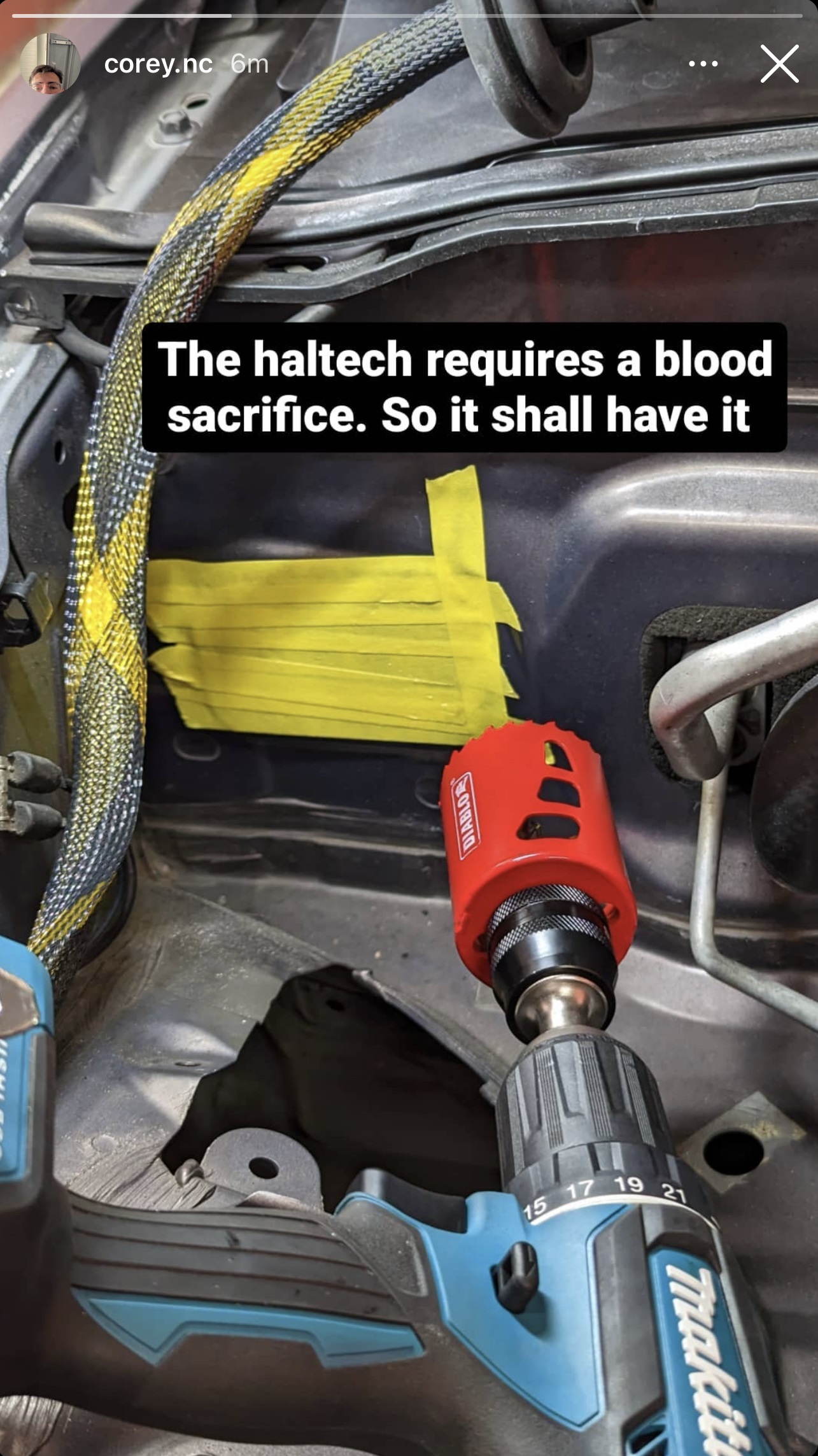
However if you do forget where a component went I’ll be sure to help if you reach out via email or social-media. The last catch of course as I’m sure you’ve seen this coming is you will need to drill a 2″ hole through your firewall and install the ecu behind the glovebox. More on that process and how I’ve achieved that now.
The install
Let’s start by talking about the first job you’ll find yourself doing. Drilling through the firewall. Which even for me at first was very daunting. However since I’ve now done the job myself I am very happy to guide you through this process from start to finish. So again my NC is RHD. Meaning I have the LHD clutch-master-cylinder flat stamped section over on my passenger side of the firewall. This is the perfect spot to drill and install the 2″ already slid over the loom Haltech grommet. Here’s the critical information. The Haltech grommet fits perfect if your smack centre of stamped section. You’ll be able to see what I mean in the photos below. Now if your thinking ahead you may be thinking shoot, there might be factory wiring running behind there right?? To your response no. Actually if you drill straight through and stop as soon as you punch through with your hole-saw then you will not contact or come close to touching any of the wiring behind that void. Now I’d suggest you use a spring-loaded-centre-punch to guide your pilot drill-bit prior to using the hole-saw. Getting the hole-saw in there is not an easy task. You may have to slightly angle the hole-saw to get it to start. Please take your time and do your best. Once you’ve drilled through successfully I suggest before you cut open your fingers from the burs around the hole. Use a deburring-tool or needle-file to clear both sides of the hole where the burs are. Once it’s safe to gain access you need to pick and pull apart the sound-deadening material away from the hole. Remove as much as you can so the other side of the hole behind the dash hasn’t got anywhere as near much sound-deadening material touching the hole’s perimeter. This is because once you’ve pick and pulled the material out of the way by means of fingers and/or needle-nose-pliers you’ll need to finish the hole with a round needle-file and once done you shouldn’t be able to feel any burs or sharp-edges around the perimeter on both sides. Great. Now using either a touch-up primer-pencil the kind used for car-bodywork repairs or using some primer sprayed into the cap and a small sponge you’ll want to be sure to cover all bare metal with the primer to ensure you never have rust issues in the future. It’s preferred to have some overlap onto your original paint either side just a bit though nothing crazy. The grommet has a thick-lip and will cover the primer and the interior finish around the hole isn’t that critical because you will never see it. But you don’t want rust forming so do a good job and take your time.
Now I may be hearing, well what about us LHD NC owners? Where do we drill through? Fortunately I have photos from a gentleman who’s recently done his. You’ll be drilling through to the left area of where your factory A/C and coolant lines go through the firewall. It is a flat section as shown in the photos below. You will have to carry out the exact same procedures as mention above but in that location instead.
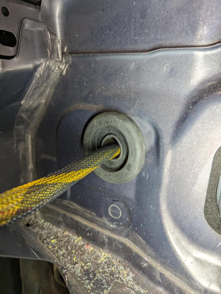
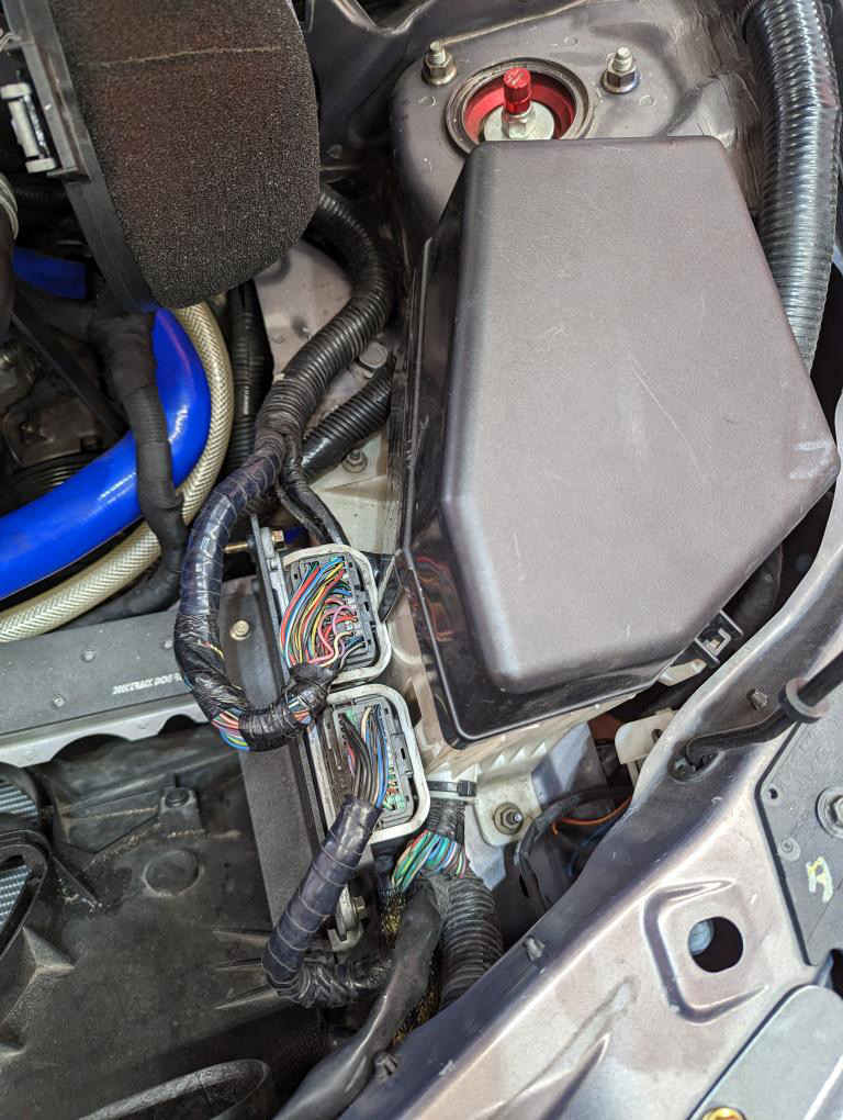
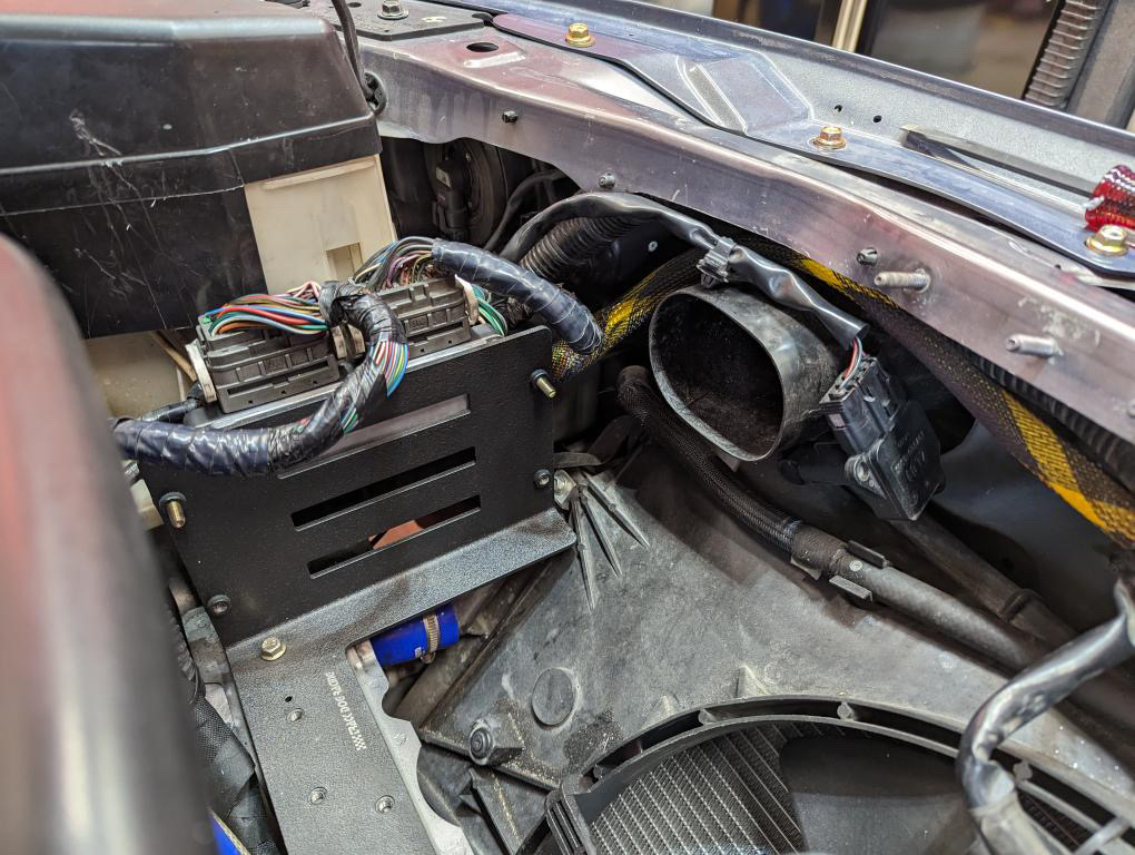
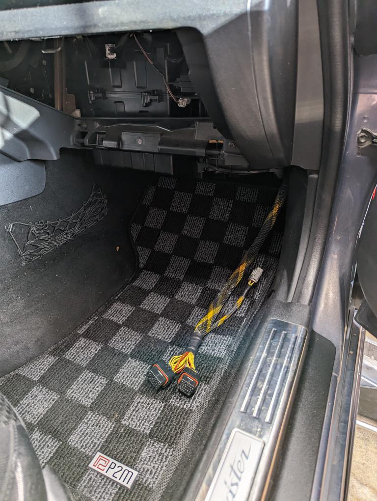
Right, so we’ve drilled out hole and the primer has had about 15-20 minutes to dry. We’ll route the two Haltech ecu connectors through very very carefully. Then we’ll get the length we think we’ll need as we route it down the back of the blower-motor assembly and under-neath the passenger footwell to the outside of the vehicle. Then we can turn up and eventually zip-tie onto the factory-wiring behind the glovebox. Now we can carefully push fit the grommet into place and don’t worry we can move the harness back and forth as we need to later.
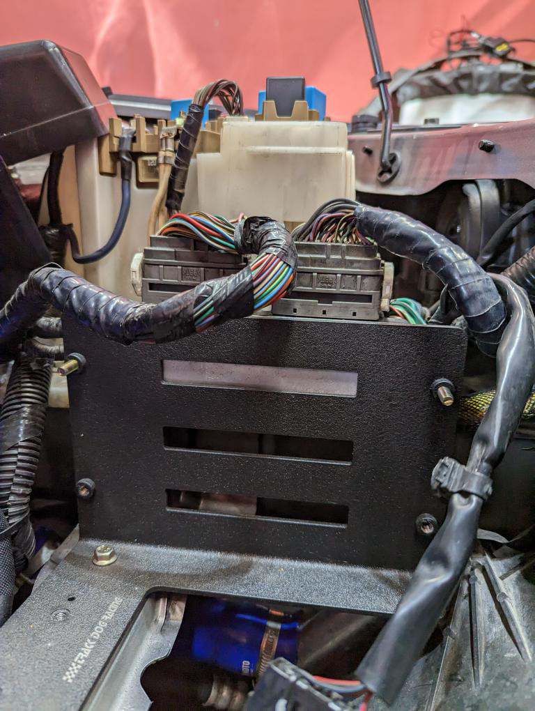
We now need to fabricate ourselves an ECU mount and cut the back portion of the glovebox out so that it may still contain the basic safety equipment like a high-visibility-vest, insurance documents, pen and paper etc but will allow the ecu and glovebox to clear each other and the glovebox door shut properly. Here comes the next catch. We do have to remove the passenger-side dash-airbag. To create enough room to fit the ecu and in my instance the CAN hub above the ecu. My bracket for the ecu picks up the two airbag M6 mounting-studs on the dash-frame-structure. It is made from 2mm thick aluminium as is plenty rigid while being lightweight and I have secured the ecu four corners via four M5 stainless-steel rivnuts into the bracket and the ecu is installed onto the bracket prior to installation into the vehicle. I used medium-strength loctite to reduce the likelihood of the ecu vibrating itself free. The CAN hub is just mounted to a flat piece of 2mm thick aluminium which is cut to follow the shape of the original airbag rear plastic. It actually picks up the factory two screws in either corner. The flat bracket actually overhangs down slightly onto the top of the ecu and that void allows two M5 stainless-steel rivnuts again for securing the CAN hub to the bracket itself and once again I used medium-strength threadlocker.
But what about the WB1 wideband NTK controller? Where does that go? In my instance since the exhaust manifold is on the drivers side since my car is again RHD. I have actually installed it onto the transmission tunnel sitting directly under where the plastic-coin-holder trim rests. Giving me plenty of length to drill a hole into the transmission tunnel to reach my exhaust where the NTK o2 sensor will be fitted. However, if your a LHD owner. Then you can also fit the Haltech wideband NTK O2 sensor controller somewhere local behind the glovebox area.
Now we have the ecu and wideband controller installed. We need to speak about the wiring and don’t worry I’ve made it super simple for you to copy my setup.
My NC’s basic wiring alternations
Before we dive head first into my modifications in my personal NC. I’d like to mention that you do not have to follow exactly what I’ve done. That said. I believe 100% that my setup is the best design and I’ve reworked it four times over the years to get to this stage where I’m satisfied.
That said. Let’s dive in. The first big and hilariously easy job I’ve done was a battery-relocation. Why? Because there is little to no room under the bonnet in the NC. So freeing up space and creating better airflow are the prime reasons. However it makes maintenance and work far quicker such as installing a new serpentine-belt. It is also changing the weight distribution of the car some. In my case with the turbo this should work to attempt to counter-balance the vehicle. Now we know why, we need to understand what I’ve done and briefly why everything is as it is. I’d highly suggest you check out my battery-relocation article then once you’ve got you head in the game come back here for more info.
Now you’ve seen what I’ve done and why. We need to explain my hidden little third-fusebox. This little guy sits directly above the second (interior) fusebox. It is only live when the ignition is on. It has six ways (available circuits). If we look below you’ll find a diagram that shows the setup. First we start at the power-distribution-box mentioned in the previous battery-relocation article. Then we go through one of the 30amp Midi fuses and through some 6mm2/10AWG wire that runs through the vehicle following the battery-relocation main power-wire route. But as we get just past the factory interior fusebox we turn up and find ourselves connection to pin-30 on a 40amp normally-open four-pin diode-protected relay. Ground is spoken for by connecting to the chassis and pin-86. In my instance from the back of the seat-warming circuit (that I have entirely removed) I use a heatshrink-lined through-connector and some 1.5mm (same as the original circuit) and find ourselves going to pin-85 completing the coil-side of the relay. Now this could be completed by using the correct-size fuse-tap instead if you wish to retain all your factory interior circuits. Then from pin-87 (the output) we go through a short fly-lead of 6mm2/10AWG to the common-terminal on the BlueSea-Systems 6-way fusebox. This is the variant without the common ground connections. That’s not necessary. Then from the new third fusebox we have a four circuits to date. Nearly all of which use a Deutsch DT 2pin connector a couple of inches from the fusebox to their opposed Deutsch connector that then run off into the field so to speak. The first circuit is the dashcam its a 5amp fuse. The second circuit is the interior-lighting-circuit which is a 3amp fuse. The third circuit is a spare circuit that is connected but not currently used intended for future use. The forth circuit is the power supply to the Haltech wideband o2 controller. This is because the single-channel wideband o2 controller can draw up to a maximum of 3amps during start-up as the sensor is in the heating-phase. As soon as you start the engine. Which means it cannot use the power from the front CANBUS connector under the dust-cover of the ecu for its power demands. Because the CAN keypad is also interlinked with the wideband 02 controller this circuit also powers that but the load of the CAN keypad is minuscule so no trouble there.
Now the main reason I haven’t decided to do a sperate article for the third-fusebox is I’ve added far too many devices to continue to use fuse-taps. More than one fuse-tap in a fusebox of that many ways looks amateur. Not to mention your leaching power from other circuits and its not a good idea. Now I mention the use of a fuse-tap for the power to the coil-side of the 40amp relay. Why am I okay with this? Because the coil of a modern 12/24V relay uses approximately 200mA or 0.2amp. Which is nothing and will not be enough to effect any circuits you have available.
Important checks before start-up
Before you attempt to start the engine you must certainly check out my “Haltech first start-up procedure” article. Failure to do so may result in catastrophic engine damage. Save yourself a head-ache and check it out. The article will be more laptop based.
RoadsterWireWorks
Before we start to conclude this article I need to mention some information about Chris from RoadsterWireWorks. Firstly, the cost of your harness may differ between LHD and RHD variants. This is because LHD owners will have a longer path to take to end up at the factory two ecu connectors. Secondly, is if you’ve made the decision after all you’ve read then you can contact Chris at roadsterwireworks@gmail.com to place an order. To save both you and Chris time. He’ll need to know if you have A/C, if your RHD or LHD and you’ll need to mention if you’ll want to convert your alternator to a self-regulating alternator or use his newer patch-harness that does not require you to touch the alternator. As mentioned above under the “Tell me more about these features” heading and penultimate paragraph, update. If you have any questions about your order Chris is a very helpful guy and believe me you can ask him questions that you may think sound silly. He always comes back to clarify for you and his after-purchase-care is top-notch.
Learn a little about VE-tuning
Now I’ve covered everything necessary for you to install a Haltech Elite 1500 and Wideband NTK o2 controller in your own vehicle. I feel it is my duty to provide you the resources straight from Haltech and other valuable sources on how we tune in VE (Volumetric-Efficiency) as you’ll learn it’s actually relatively simple. The ecu does most of the leg-work. Below our some videos I strongly suggest you watch and if you have any questions search the Haltech forum or web to truly understand what’s going on.
The end
If this article has been helpful to you do me a massive favour and share it with your NC pals. That would be extremely helpful to share the knowledge and make the NC platform more common-knowledge. If I have missed something you think is absolutely necessary to mention in this article please reply down below and I’ll consider adding anything I’ve missed that may be of use. If you’ve come this far then thank you. You are the reason this site works by sharing the knowledge.
Join the discussion