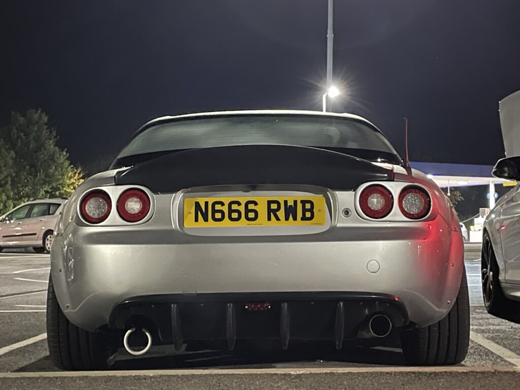
CarbonMiata NC Quad LED brake lights
Written by
What a lot of effort. Let me explain…
For those that have been following me on the socials you’d probably know all I’ve had with these lights is trouble. For those that are unaware or newcomers and have come to my website interested in these lights. Welcome. This article will be a hybrid of a review and solution to how I and many other CarbonMiata customers went about installing these from start to finish and the drama along the way. Hopefully once you’ve read this article you’ll be able to make an informed decision if these are worth your time.
First impressions out of the box.
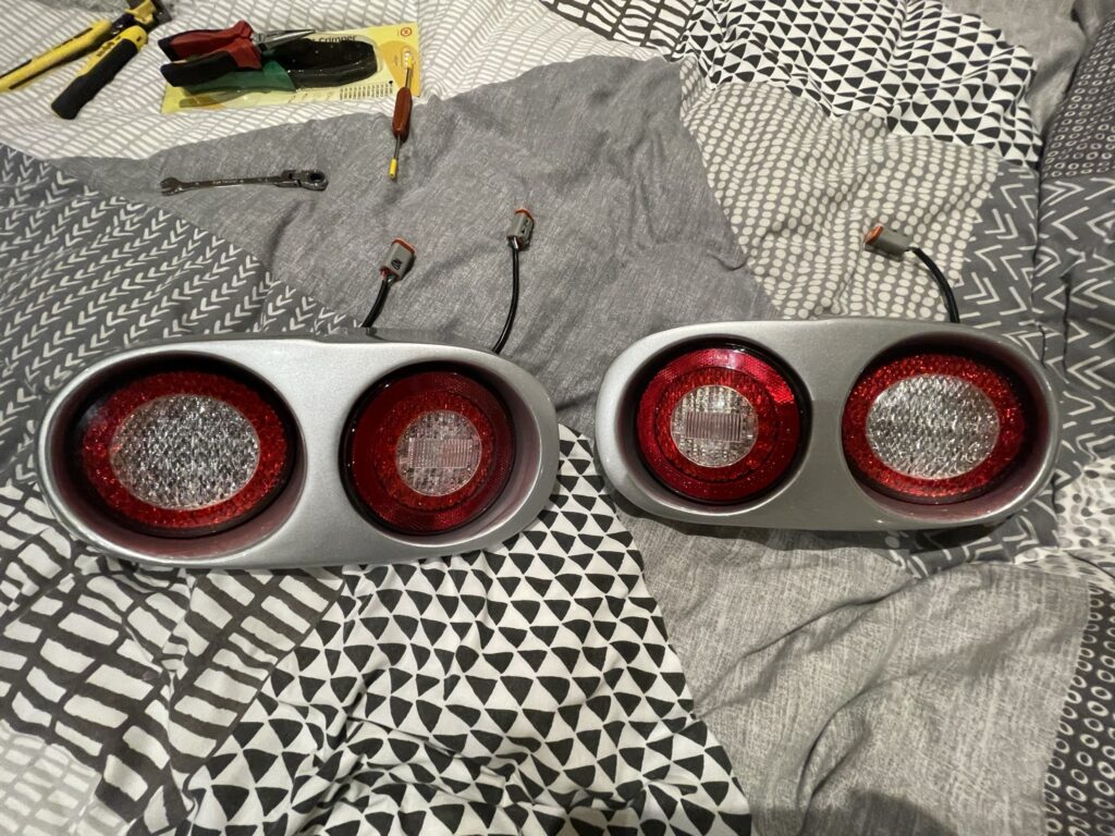
Upon receiving them and opening the box up, they appeared to be in good condition. Before I purchased these, I heard a lot of bad and mixed reviews in both the MX-5 Europe and NC Miata Facebook groups. So, I had a little insight prior to purchase. So, what did I notice? Well, the lights came as complete units with the LED round assemblies installed into their respective side fiberglass housings. Problem is the hole that had been drilled centre between the two M6 studs that are integral to the LED assemblies was too small. Because of this the slight misalignment of the LED assemblies meant the installer had slightly pinched the cables that came out the back of these LED assemblies. Not ideal at all.
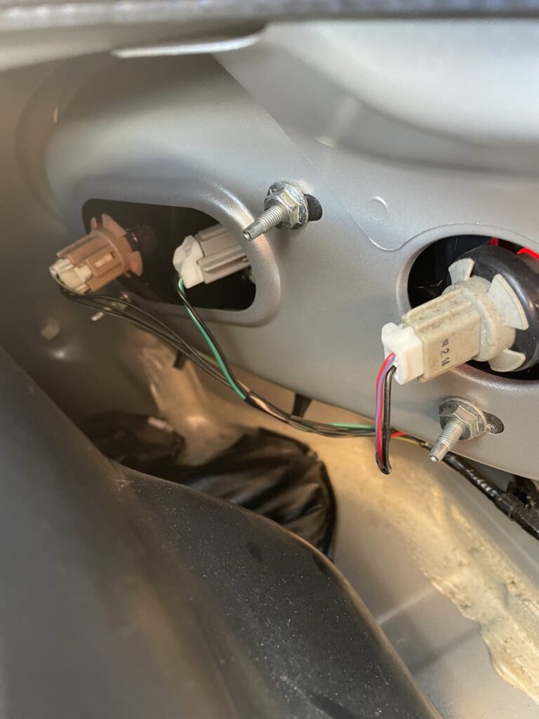
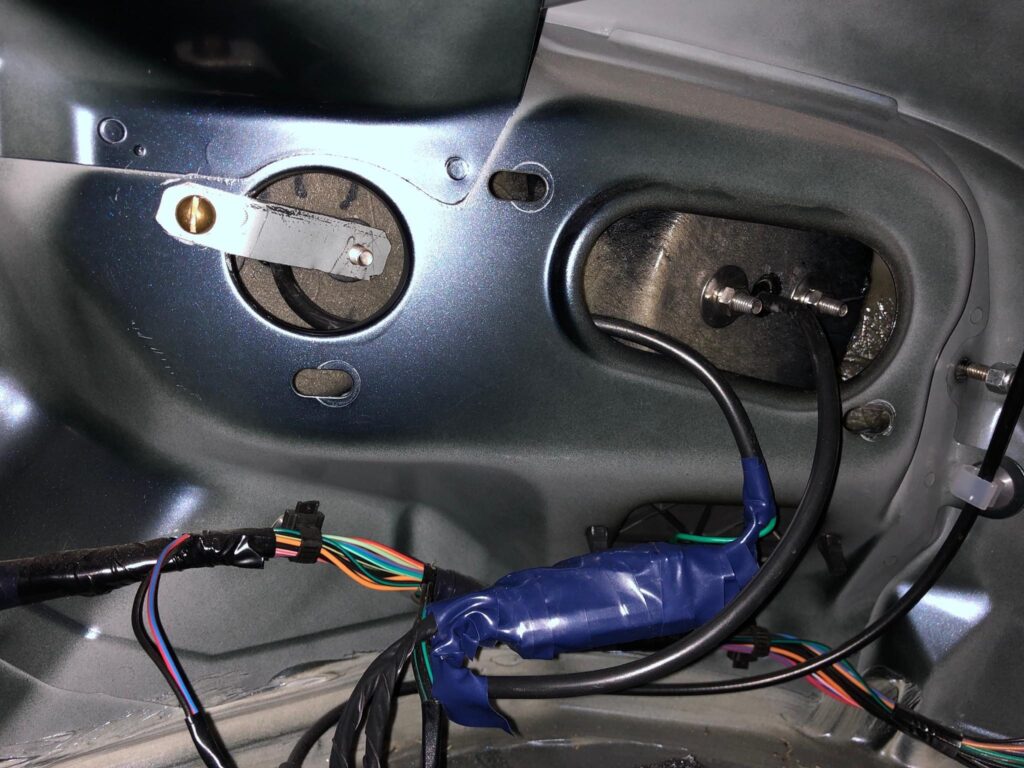
The next critical issue I quickly identified was the fixing method for these lights. They come with one M6 gutter-bolt that is cured with resin inside a tab that replaces a factory locating pin. (You must remove that white plastic seal to install these). I was very confused at first as I was not sure how the Mazda brake lights were attached at the time. But I was worried. I thought surely these lights were made specifically for a Mk3/NC MX-5 so they’d provide a proper mounting solution to secure these to the vehicle. No. They don’t.
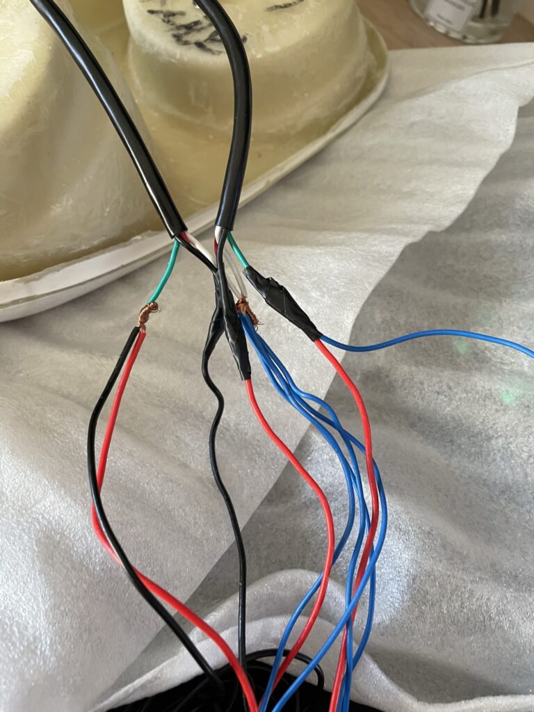
The final critical issue I came across was the damn right amateur wiring. The harnesses that adapt your Mazda light holder connectors to the new CarbonMiata was a twist and tape connection. No crimping, not even any soldering. Just twist and tape. That was it. They came taped up in this horrendous 3M electrical tap. I was even more shocked when I found this out and was flabbergasted considering the cost of these were $365 excluding taxes and shipping to my country. I paid a lot of money for what these are for them to complete the terminations by twist and tape. I was shocked quite frankly…
If you think that was where the wiring issues ended boy, you are dead wrong. To fully disassemble the respective side brake lights, I had to undo all the installers wiring to be able to easily separate the two LED assemblies (per respective side) so that the housings could be given to my body and paint gentleman to do his work. It would be impossible to do a thorough paint job on these housings with the LED assemblies remaining installed. Since they are such a snug fit. Again, not ideal.
More details…
Now for the technical details. I will keep this straight to the point.
The brake light housings unlike the Mazda brake lights do not come with a foam gasket that seals up to the stamped-out section in your boot where your factory lamp connections are. In fact, they don’t provide absolutely any seal whatsoever. You can see the lack of detail and thought being a common occurrence, can’t you? They do not recess back like the Mazda ones do which of course leads to the boot compartment not having the same sealing as it did out of the factory. Which leads to moisture issues and could potentially lead to water ingress. A serious problem!
As mentioned earlier these brake light housings only come with the one M6 stud fixing. You absolutely cannot just secure these using that one fixing. They’d never sit back snug without a second fixing point. So not only for $365 they come with a twist and tape wiring method. But they also come with half the fixings included needed to install these. Nice job CarbonMiata. It’s bad enough that you’ll have to rewire these to begin with due to poor foresight. But you’ll also have to fabricate yourself a fixing bracket. One that should come with the light integral or be supplied with the pair of brake lights from CarbonMiata themselves as a separate item. You will be amused when you see what sort of bracket is required to fix the poor design of these later. But the cost for the material of these brackets is minuscule.
Wiring.
As mentioned at the start of the article. The twist and tape termination method took me about an hour for a semi-professional like myself to carefully unwrap and unpick the awful wiring. While creating a rough wiring diagram to transpose the lamp connectors to the LED assembly tails. Not forgetting the included 50Watt resistor. If you’re someone who indulges into vehicle wiring or any 12V/24VDC system, you’ll be confused when you see the wiring colour choices for wire designation. For those unfamiliar, solid red is usually 12VDC while black is GROUND. Then you use other colours for different switch-lines. However, on these they have used blue as your GROUND path. Which makes for an annoyance when the harness is nearly complete and either sleeved up, heat shrunk or fleece tapped up and your confirming final terminations for correct pinout.
After I had fully dissembled and created myself a wiring diagram to understand how they were intended to be connected for correct light operation. I realised it would be ideal given the current draw of these lights compared to the Mazda incandescent lamps, to provide each LED assembly with only one ground. This is fine and how each LED assembly was designed to be connected. After I had decided the correct way to terminate these. I went and purchased the best connectors you can readily buy to make these a modular setup. I am of course talking about the awesome Deutsch connectors. Specifically, the DT series. This would mean I could create each respective sides (Left and Right) brake light harnesses on the bench. While importantly being able to swiftly de-pin and re-pin the tails from the LED assemblies to make install after they came back from paint a walk in the park. I will mention now, I did use a round-file to open the centre hole for the cables by about 5mm to avoid that misalignment pinching issue. Where it left an impression on the cable. No issue anymore.
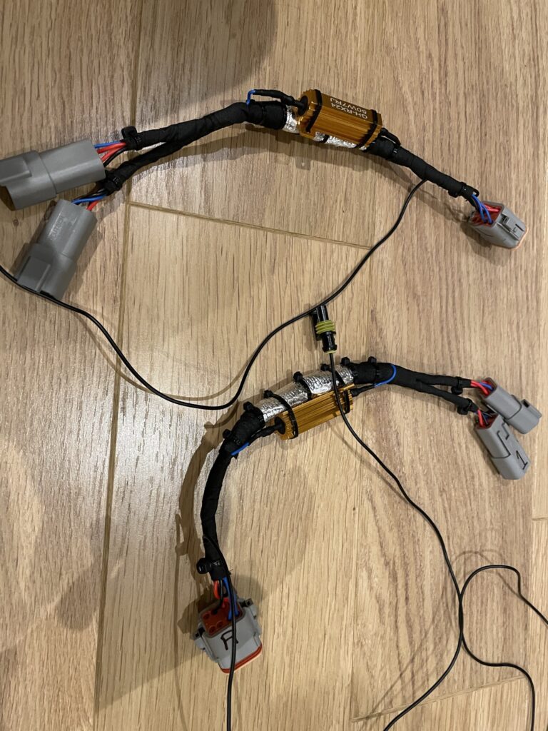
I wanted a one plug connection method to remove the light from the body-side wiring. I opted for a Deutsch DT 8pin connector kit (Male and female with corresponding pins to crimp). These 8pin DT kits came to approximately £10 each. I of course needed 2 kits (2 male, 2 female) for both sides. Why 8pin not say 6pin? At the time I wasn’t 100% sure on some final details. I ended up simplifying the wiring further and needed less ways. So as someone who wishes to mimic my setup. You’ll be perfectly fine 6pin DT connector kits.
It goes without saying, I have cut the lamp holder connector ends off and have put them all in the Deutsch DT 8pin connector. Minus (spoiler alert) the right brake light fog light connections. These were put into a separate Deutsch DT 2pin connector. More on the rear fog light later.
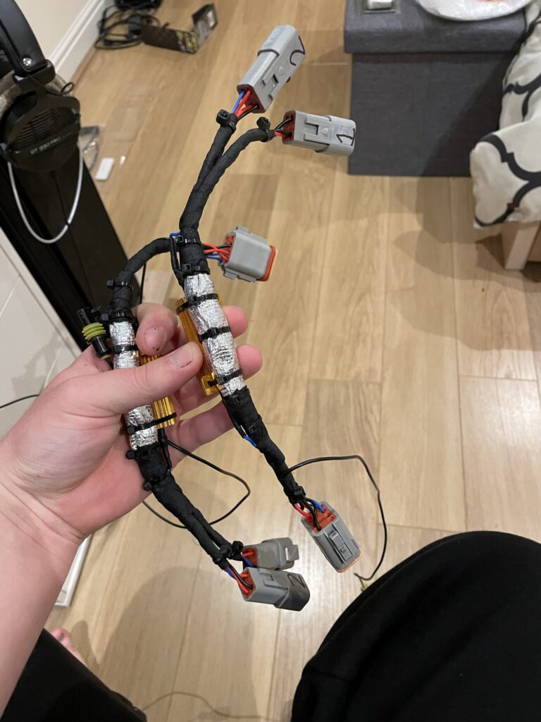
The harness section itself is wrapped up in tessa fleece tape. This product is designed for interior use and works very well. I have used regular tessa auto electrical tape to bunch the wires together underneath the fleece tape. While also using it to tape the section where the silver heat sleeve is installed underneath two complete windings. To create a layer to avoid the stray glass fibres potentially cutting though the wiring over time and vibration. Then used to secure the very ends of the silver heat sleeve down before finally going over the heat sleeve ends by going over the whole harness again with tessa fleece tape to make it look discrete and professional. I’d recommend you use some silver or gold fiberglass backed heat sleeving around the area the resistor will sit back against. Because if you sit with your indicators or hazards on for a prolonged period then these do get too hot to touch with bare hands.
Which leads me onto why we even need the 50Watt resistor first anyways?! Well. Your cars oem flasher module has a function whereby it will flash twice as fast on a lamp that the system feels is about to blow the light element soon. This is done because the flasher module will sense that lamp is drawing far less current than it usually is. This feature is called “hyper-flash”. If your familiar with LED’s. They consume less than a 1/10th of the current of an incandescent lamp. Which is why they last longer since they don’t draw a lot of current, so they do not get that hot. So, they won’t burn out as fast. While also taking less drain off your vehicles electrical system due to the less current draw. But in this instance on our indicator and hazards circuit this will cause the hyper-flash feature. Meaning your LED indicator will be flashing twice as fast. We solve this problem by using a 50Watt (5 amps @ 12VDC) resistor wired in parallel across the load (indicator switch-line and ground). So once the circuit is energised the resistor is fooling the Mazda flasher module to think the vehicle still has incandescent lamps fitted on the indicator and hazards circuit. It simply turns that current into heat. Thus, my effort to protect the harness and anything in the boot from them. Including plastics, other wiring and metallic surfaces.
That’s it for the electrical point of view.
Making them ACTUALLY fit as advertised.
For those that are in the know. Yes, these are indeed advertised for the NC3.5 and NC3.75 face-lift models. But that is immaterial to the fact they only come with one fixing point. This point only justifies the ever so small and different shape Mk3/NC1 bumper gap with these brake lights. Which CarbonMiata do mention somewhere.
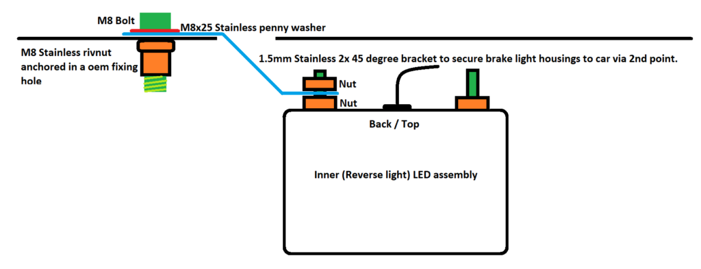
So, what’s my solution? Well, it’s a simple bracket made from 1.5mm 304 stainless sheet metal. Bent like the diagram below. Two 45-degree bends and that’s it. I pick up the inner (from centre of bumper) stud from the LED light assemblies sticking out the back. Then I used the existing fixing hole and used a M8 A2 stainless riv-nut and bolt (what best fit the existing hole). to attach the other end and bolted it through with a A2 stainless penny washer on the car attachment point. This solution is solid and is plenty rigid.
The oval shape opening has some metal-spined rubber weather-strip around the edge with the wiring passing through for both LED light assemblies. I have not yet found a suitable way to seal these openings up to combat moisture in the boot compartment without making brake light removal for when you need to remove the bumper for instance a pain and troublesome.
What you thought I forgot?
Disclaimer: I’m no legal professional, contact a legal expert or mechanic if you are unsure.
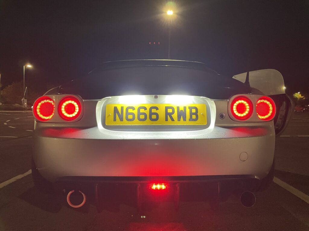
To solve the fact both passenger and driver side lights are now both reverse lights. We relocate the rear fog-light *(UK MOT required)* to the centre of the rear diffuser. This is compliant with MOT regulations. The LED fog light I purchased can be found here.
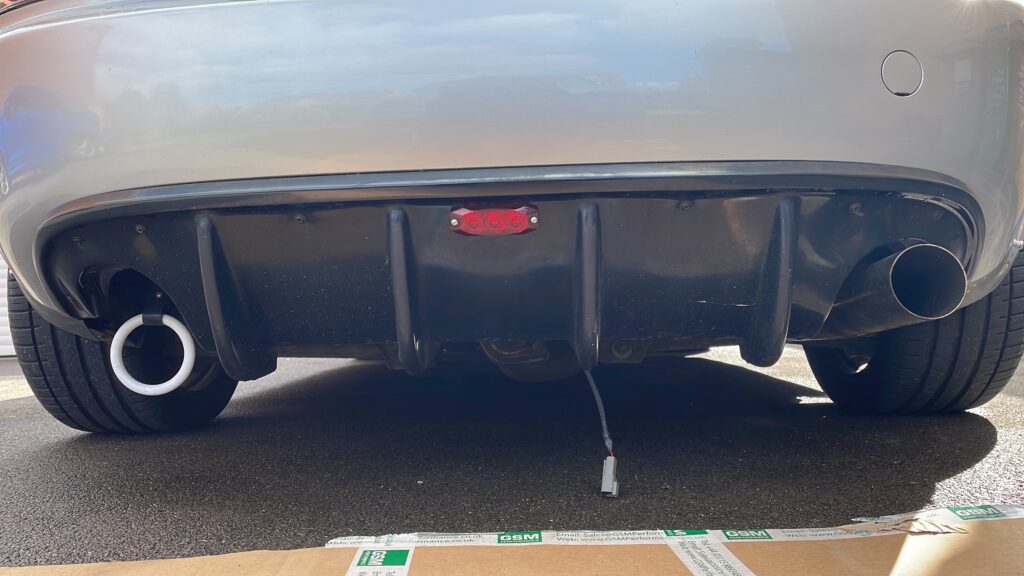
For this I took a ground (black) on car body-side and the rear-fog light wire and put it into a 2pin Deutsch DT connector kit. Then run the wiring through the back void that has now been created behind the stamped chassis section where the foam seal used to be down under the bumper. Then it goes to another identical 2pin Deutsch DT 2pin connector kit (male + female) under the car and sits in a mount for the connector to keep the wiring tucked out of the way. Reasoning for two connectors is both servicing and maintenance.
Conclusion
So if you’re in the market for aftermarket brake-lights should you consider these as an option? Well if you’re wanting a plug and play wiring solution and bolt-in design with no extra work needed to fit them then I’d have to say these are not for you. However if you’re okay with having to re-wire and create your own mounting brackets to fit these at the cost of, in my opinion a slightly better looking rear-end then these are worth it. My final thought is these should not cost nowhere near as much as they do and CarbonMiata should offer these with the mounting bracket supplied and the option to for the customer to wire them up for a slightly less cost of the units pre-wired to work with oem lamp connectors.
I hope this article has been highly useful for you to make an educated decision on whether these are worth your hand earned cash. Or if you should look elsewhere for a more honest solution. As always, any questions don’t hesitate to ask in the comments to this article. Thank you for reading this far and have a good day.
Love the lights but it’s a shame they need so much effort to get them to fit. I always thought CarbonMiata was a quality brand but after reading your post I have my doubts…
Hi Rob, yeah it such a shame because the design and concept looks good but I am still yet to sort a solution out for the waterproofing and sealing the boot/trunk stamped sections as lots of moisture tends to form in the boot now. Obviously I could tape it up but that’s a non-permanent solution and amateur at best. Compared to the factory brake-light seal.