Turbo NC custom wastegate-actuator
Written by
Why custom?
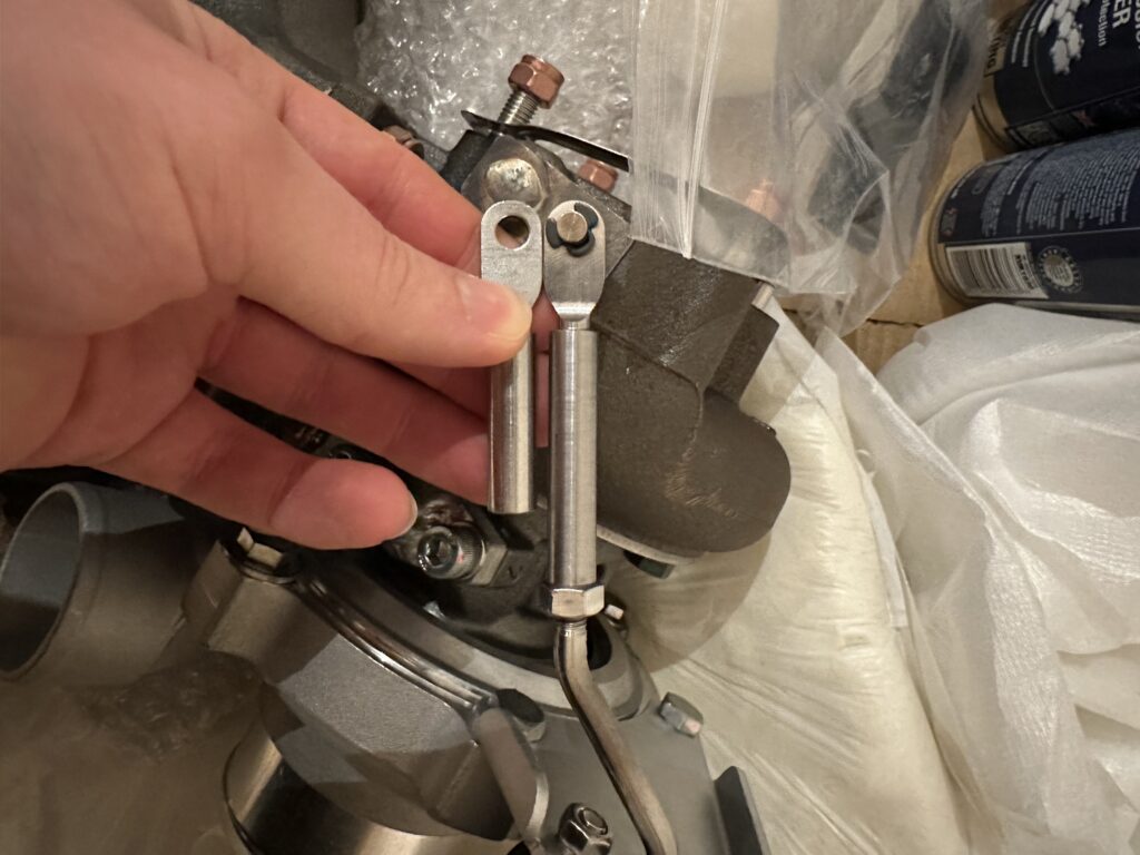
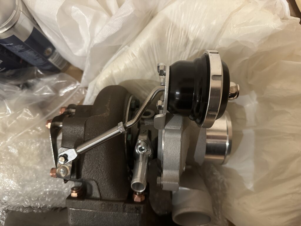
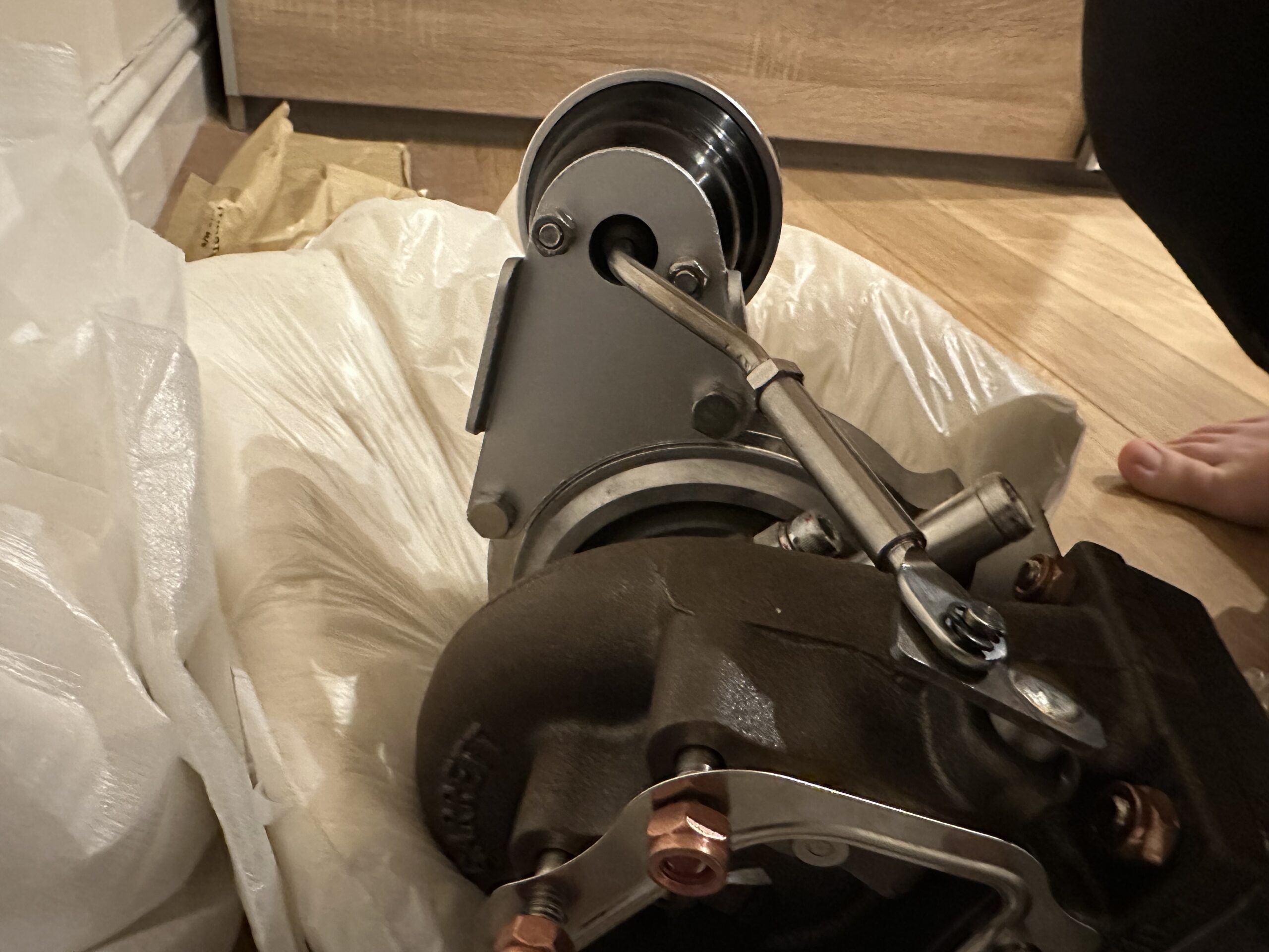
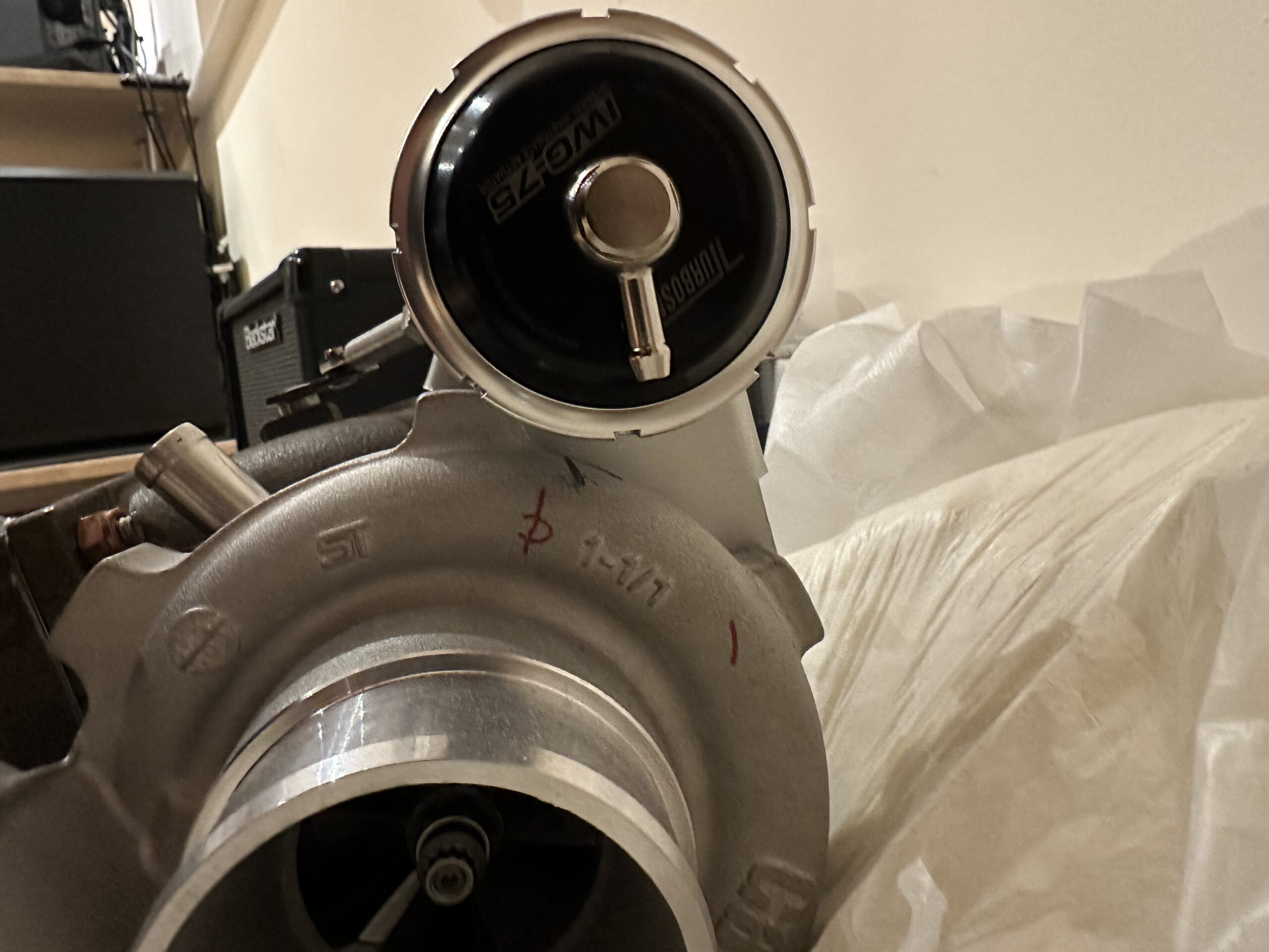
So, prior to offering the turbo and manifold combination onto the engine. It is comprised of a new Garrett T25 GT2871R 0.64 A/R bolted to a Kraken cast-iron top-mount manifold. I have purchased a Turbosmart IWG75 to use in conjunction with a three-port MAC valve (Part No: 35-AAA-DDBA-1BA). The IWG75 came with a GT2871R specific bracket. Unfortunately, due to the location of the stock braking-system, the ABS hardlines from the ABS-module on the 45-degree section would foul in either position where the supplied rod and clevis could reach the welded wastegate-door-arm. Please see photos later that show the fouling issue.
I ended up settling on using the supplied bracket with the new actuator. Rather than retain the factory Garrett bracket. However, I raised the bracket up one bolthole clockwise. In turn, this rotates the turbine-housing-clamps. This created two new problems. The first issue was that the stainless-steel rod from the actuator was no longer facing straight towards the clevis-attachment-pin. This was a minor issue. The second issue is that the factory Garrett 50mm clevis would come up short.
IMAGE SLIDESHOW HERE OF HITTING BRAKE LINES
So how did I solve those two issues?
I had to bend the stainless rod out more to widen the angle. I did so by completely disassembling the actuator-body. I didn’t have the correct type C-spanner, so instead, I ended up using a cleaner rag and vice-grips to carefully loosen the outer ring. It worked a treat. I then held down the top-hat of the actuator-body while completely removing the outer-ring-clamp. Slowly releasing the compressed parts carefully. Prior to completing the disassembly, I removed the factory Garrett 50mm clevis and 1/4” UNF nut from the rod-arm. To continue further with the disassembly, I went into the garage to use the vice. I held the rod in the vice to make sure to lock both bends in the jaws on their sides. This way, as I removed the piston and spring assembly, the rod would not move. I removed the piston and spring assembly by putting a spanner through the spring windings and picking up the square flats at the base of the piston. With a little bit of elbow-grease, I freed the piston. Then disassembly was the same as removal of all the other compressed parts before. I set the spring and piston assembly aside and made note of the colour-markings on the spring for future reference. This confirmed my suspicion, it was a 7psi spring. If you’re unfamiliar with aftermarket actuators, the main reason I chose this unit is so I can increase the base-boost-pressure value. The factory Garrett unit is non-serviceable, so there is a fixed rate spring. I removed the rod-arm from the vice. I traced its profile on a piece of cardboard. I then drew the increased angle I needed from the original point after the bend. So, I had a target to aim for. I placed the rod back in the vice again but threaded-on the 1/4″ UNF nut and clevis in order to gain more leverage. Using a mapp-gas torch, I pre-heated the bend until it was hot, but not glowing hot once I removed the heat. I found by using a large spanner, I could apply more leverage without having to directly touch the part. This allowed me to carry out the bending action to the desired increased angle on my cardboard template. This process was trial and error, fine tweaking the bend. Finally, achieving the desired angle. Then I reassembled the entire wastegate-actuator-assembly back together and onto the turbo for a trial fit. I had achieved the angle I needed in situ and would pick up the wastegate-door-arm straight and while I waited for my new longer clevis to arrive, I disassembled the whole thing again. This time, applying some red 242 loctite on the end of the male thread that went into the pistons base thread. Offering the rod and piston and spring assembly back into the vice and tightened it using a spanner and getting onto the flats. Once this was done, I reassembled the entire assembly and installed it onto the turbo and waited for the longer clevis to show up.way,
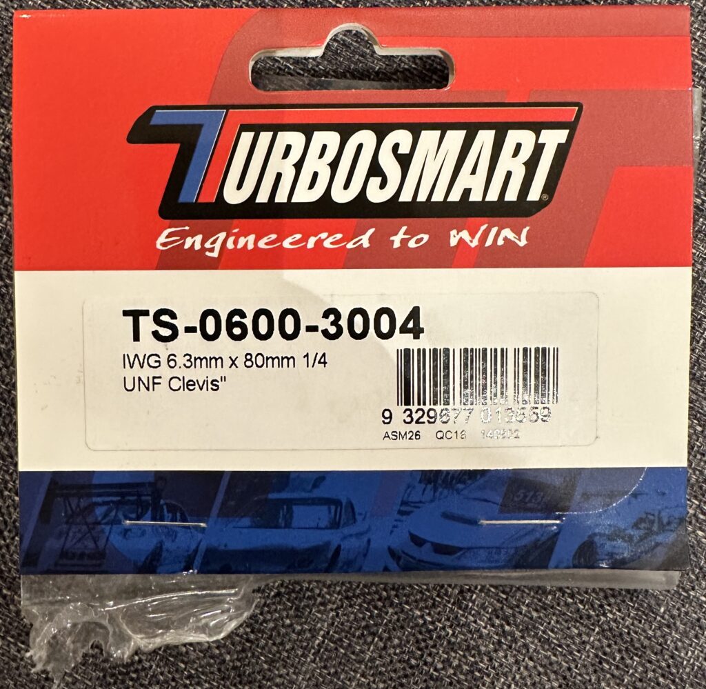
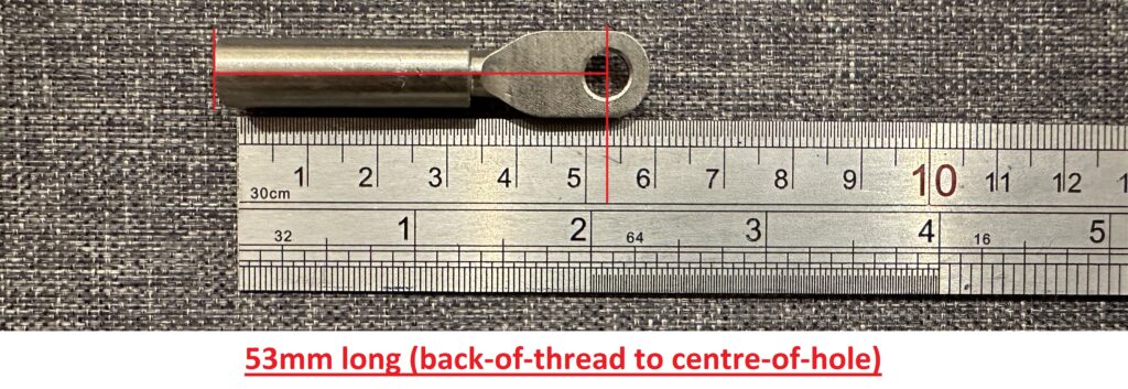
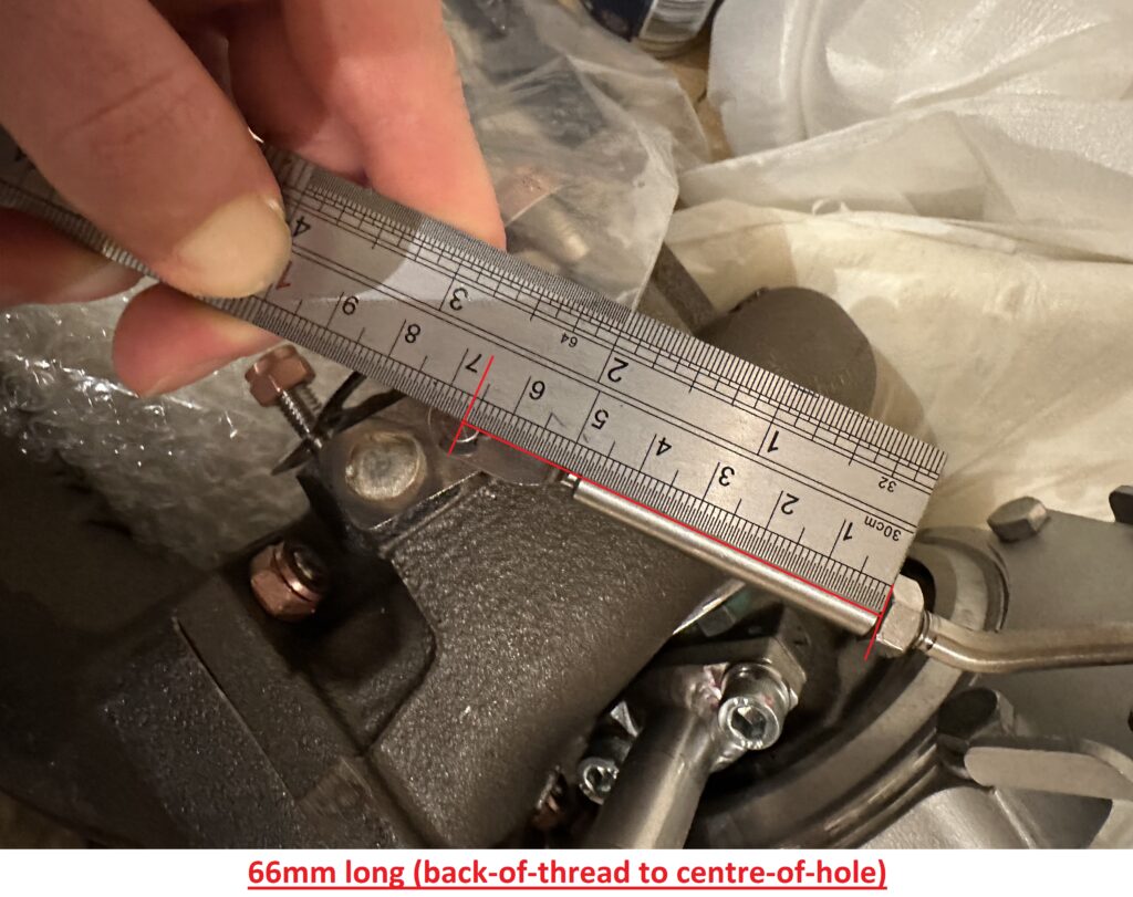
I knew I needed a much longer clevis. Fortunately, Turbosmart sells longer clevises. I ended up buying it through Tegiwa-Imports here in the United Kingdom. The part number I ordered was “TS-0600-3004”. This clevis has a 6.3mm I.D. hole for the wastegate-door-arm. The thread is 1/4″ UNF and the length was 80mm long. I ended up cutting that down to 67mm long (back-of-thread to centre-of-hole). The original Garrett clevis was 53mm long (back-of-thread to centre-of-hole). As shown in the photo below.
To shorten the length of the originally 80mm long clevis, I preceded to use a ring of tape. To get as square and straight of a cut as I could with the tools I had on hand. I put the clevis in the vice and cut it with a regular hacksaw and 34TPI blade. I then began to file up the circumference with one of my Bahco needle files. It cleaned up well. The only negative is that shortening the clevis this way means I have lost the 2mm countersunk clearance hole. Meaning it makes starting the thread harder and, without more attention, you could easily cross-thread onto the rods male thread. I trial fitted the clevis and found out it was too long. So, I ended up extending the thread down the clevis as it was only partially-threaded as it was originally a longer clevis and I had chopped some of the threaded section off. I did this with two taps from my favourite place for taps and dies in the UK. TracyTools. They are not a sponsor but are my go-to source for taps and dies. The two taps of 1/4” UNF thread I ordered were a HSS plug and HSS taper tap. The tap wrench you’ll need to use these taps is a 5/32” – 1/2″ tap-wrench. I started using the taper-tap and cutting-grease, while turning to threads clockwise. Then two threads counter clockwise to clear the tap from chips. I did this procedure twice before removing the tap completely and clearing the chips off of the tap itself and clearing the blind-thread base from all the chips that had fallen down. Then I started the whole process again. I repeated this whole process about three times until the tap had bottomed-out. Then I swapped over the taper-tap to the plug-tap and repeated. After the thread was extended, I used a pick and some water to rinse all the chips out of the female thread. This took about ten attempts till the threads were free of stainless chips. I trial fitted the turbo and found I was about 2-3mm too long still. So the logical procedure was to remove about 2-3 threads off of the rod-arm threaded-section so I still had as much thread engagement as possible. This was because I needed my 3mm pre-load as Turbosmart suggested with the IWG75 instructions. Trial fitted again and it worked perfectly. With about 3-4 threads left on the rods threaded section after the nut.
Awesome. It finally worked out. I then, later the next day, trial fitted on the car since the relocation of the wastegate-actuator, and it fit a treat. I have about 5-6mm of clearance from the ABS lines as they were from the factory. If I ever have any contact with the engine moving on the engine-mounts in the future, I can tweak the lines in situ by a minute amount to give me even more clearance. In the future, I wish to change to harder engine-mounts anyway, so that should eliminate most of the engine twisting under load then releasing back like a spring to its original position.
Join the discussion