The proper NC MX-5 battery relocation guide
Written by
Hold your horses!
Before we can get into the steps, you’ll need to complete your installation you need to step back and understand the system before installation. This will cut down the install time for you and should give you a better understanding of why and how the system works. So should any problems occur during the installation or in the future you’re fully equipped to diagnose it.
The diagram below summarises the entire setup. This setup is identical to my car. Working away from the positive battery terminal. We make the first stop at the power distribution box. This neat little box is configured as in the image attached below. As the positive path enters the power-distribution box it splits. One path runs through a 200A mega fuse, and the other path is used for additional circuits that are not related to this battery relocation. As we continue, we leave the power distribution box and head onward to the front of the car. Once we get through the firewall we connect to a three-way power-distribution joint box. The starter motor/alternator leg, a 25mm2 high-flex cable, has a crimp lug attached and connected to the joint box. The last leg is new. This leg replaces the fuse box main supply. This new leg is a 16mm2 high-flex supply. I uprated this leg as I couldn’t clearly determine its original size. From the joint box, we have a 16mm2 crimp-lug that goes directly to an inline midi fuse (with a 125amp midi fuse) (please see pictures to best understand). Then from there alongside the oem wiring loom under the bonnet. Then turns off near the main fuse box and goes to a 90-degree 16-6 crimp lug. Then attaches to the OEM connection point.
The original engine ground is simply replaced with a tinned-braided ground cable from its original bracket on the engine to the original cross-member grounding point. Which coincidentally has a ground symbol beside the M6x1.0mm female thread.
Now we’ve covered the circuit design. Head to page three using the navigation directly below for the install guide.
Hello,
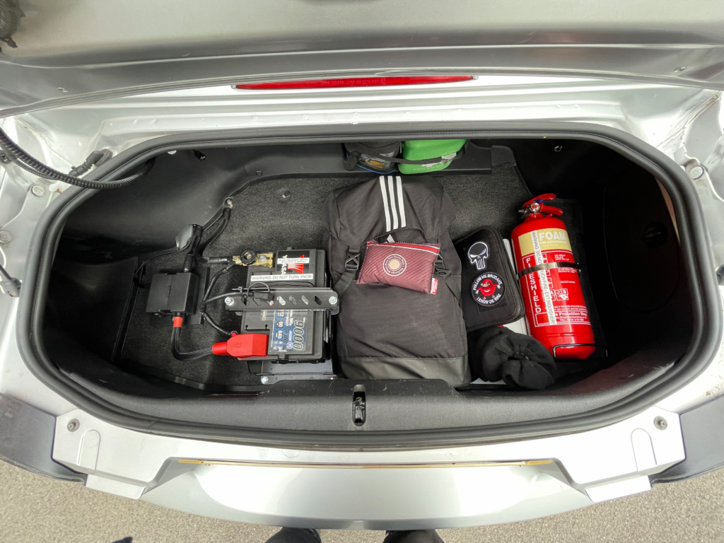
Looking at your boot/trunk mounted battery in your NC, your conversion looks far better than any other solutions from various vendors I have seen here in the States. It even looks more complete than the factory boot/trunk mounted battery locations in other versions of the MX-5 Miata!
I was wondering if you have additional photos and information (eg, actual routing position of the cable) that shows the installation from the boot/trunk through the passenger compartment, and also the connections in the engine bay. Thanks in advance!
Hello,
Your boot/trunk conversion for your NC MX-5 looks like one of the best shown on the internet, even rivaling the factory installations in other versions of the MX-5. I am curious, and no doubt other readers are, on how you routed the primary and secondary cables through the passenger compartment, engine compartment, and final connections to the starter and other items in the engine compartment. A description and additional photos in these areas would be really helpful to those of use who wish to replicate your installation. Thanks so much!
Hi,
I will in the future upload more photos in the engine bay. But put simply a 50mm2 through-crimp connects to the two cables that would go to the battery terminal. Essentially two cables join to one. I penetrated through under the oem wiring grommet.
EDIT 01/04/2023: I have since decided it would look neater and be far better to put the battery-cable through the firewall through a 32mm open grommet that has a 3mm thick groove to accommodate the rather thick firewall.
Hi Tod,
Sorry for the really late response. I’ve been sorting my own full turbo kit for this car. So has been very hectic. The main 40mm2 power wire runs underneath the fuel-neck filler shield (behind the plastics) (this shield was cut with tin snips, and I used some metal-spined weatherstripping to prevent it rubbing and chaffing the plastic conduit the power wire is inside). Anyways, it then follows past to the left gap where the oem wiring goes past the rear left shock and is cable tied onto the oem wiring alongside in (RHD case) the passenger (LHD driver side) kickplate area and up to the main firewall grommet. That should be of enough description to explain how to copy exactly how I did mine. I’ll upload more photos soon. This is my final revision of the best way to do the battery relocation on the NC chassis that I’m 100% happy with from a design point.