The proper NC MX-5 battery relocation guide
Written by
Let’s get cracking
Step 1 – Removing plastic-trim
Start by removing the passenger-side kick-plate, door trim, rear of seats plastic panel, interior-fusebox-trim and cover, boot front and rear plastic panel, and boot left plastic trim.


Step 2 – Modifying the fuel-filler-neck-shield
Where the factory wiring comes underneath the fuel-filler-neck shield mark the area shown in the photo below. Unbolt the shield, then cut the leg highlighted in the photo off and cut the area you marked off. Drill approximately six to eight 3mm holes above the area you’ve cut off. File and clean up any burrs. Clean the shield down with isopropyl alcohol or thinners be sure to remove all foreign loose material. Then take the shield to a suitable area to spray the cut and drilled parts of the shield with spray paint to prevent rust. Return to here later once twenty-four hours have passed and the paint is fully dry.
After twenty-four hours have passed, we shall continue with the shield. Measure and cut the metal-spined-weatherstripping to run along the bottom of the shield as per the photo above. Make sure both ends that are cut do not have a spine of metal u-channel exposed. If so, carefully remove it to make the end of the strip blunt and safe. Once done fit to the bottom of the shield. Then using 2.5mm diameter cable ties go around the weatherstripping with the cable ties and tighten then snip the excess of flush and blunt. Either using some flush-cutters or a Stanley blade carefully. This is to ensure the weatherstripping never falls off. Install the shield back over your freshly protected cabling.
Step 3 – Drilling the firewall hole.
Using the photo above mark and drill out the hole through the firewall for the cable to protrude through. File and clean to ensure there are zero burrs. Clean the swarf that has fallen behind the dash out with a vacuum, then clean the swarf below the hole under the bonnet. Then clean the lip of the hole using either isopropyl alcohol or thinners to remove any grease or surface contamination. Using a primer-pen paint the outside and inside lip of the hole to prevent corrosion. Then after about ten minutes insert the cable grommet into the hole. It should be a tight fit. Ensure the lip has fully spread out on the outside and inside by feeling for it. Now the grommets are secure and ready.
Step 4 – Preparing the power-cable.
Measure to the best of your ability the cable route shown in the photos above with the plastic conduit. Then cut the plastic conduit and check both ends are not sharp. If so, cut a little off the end and try again. Then insert the cable into the plastic conduit. Allowing approximately 4″ inches at one end. Using Tessa electric tape tightly wrap around the conduit and slightly overlap the tape width onto the cable. Then using a 2.5mm diameter cable tie secure the cable tie over the overlapping tape section to avoid the tape unwrapping. Leave the remaining amount on the other end and that’ll be the end that goes into the boot, and we’ll need about half a metre for our ground-strap to the chassis. So do not cut any off. But instead, tape that ends up the same with a cable tie.
Step 5 – Fishing the power-cable through the interior.
Route the pre-loomed power cable through the interior as per the photos below. Use a regular cable tie and use the length of the cable tie as the spacings for the cable ties while adding additional ones to the corners to secure it neatly.
Once you’ve routed it to the boot of the vehicle, you’ll have to use a draw-wire. This can be anything from some old pneumatic tubing or hose that is flexible yet has some stiffness so you can route through from the engine bay down behind the dash. Once you have enough in the passenger-side footwell then using electrical tape tie the pre-loomed power cable onto the DIY draw-wire and carefully feed the cable through while you have someone slowly and gently take back the slack on the draw-wire and then begin to pull the draw-wire until he or she receives the end of the cable under the bonnet. Then continue to feed the cable until you have taken it all in but DO NOT make this tight. After pulling back about 1″-1/2 inch so the cable isn’t tight going through the grommet and there’s no tension. Always leave a little slack in some areas.
Step 6 – Mounting the battery enclosure.
I will not go into detail here because the size battery you opt for, and your placement may differ from mine. However, at least four M8 8.8 BZP nuts, bolts and washers are required. What is essential though. Is if your battery enclosure is aluminium, not steel. Then you will need a layer of rubber sheeting underneath to space the enclosure off the steel floor. What is even more important though is you use nylon shoulder washers to isolate the steel threads from the aluminium otherwise you’ll have galvanic corrosion. Ask me how I know. You want the aluminium to be completely electrically isolated from the steel chassis. I used the left-over rubber sheet to fill the base of the battery enclosure. So, the battery would not damage the enclosure’s paint during installation and removal. I made sure to use the bolts from underneath up so the thread was in a cleaner environment. Then I used some M8 nut covers on top, but I also sprayed the exposed BZP fasteners in ACF-50 and put the caps on to retain them.

Step 7 – Mounting the distribution-block under the bonnet.
Now you’ve got the other end of the power cable out under the bonnet. Let’s mount the three-way power distribution block onto the firewall. From memory, this is a M6 bolt required. Use washers and a nylock on the backside. Be sure to vacuum up all the swarf and use some primer-pen on the bare hole before bolting it back to stop future rust issues.
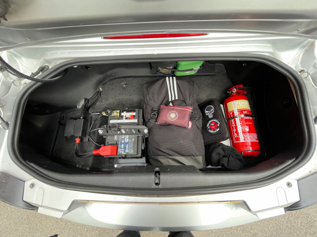
Step 8 – Mounting the MTA fused-distribution-block in the boot.
Before we crimp the lugs on the link (which is the cable that goes from front to back) we need to mount the MTA power distribution box in the boot. This is done by using riv-nuts. In my instance, because I have revised my setup several times now, I previously had mounted a different fuse-holder, so I used some 12mm thick ABS block with M6 countersunk screws underneath the MTA unit to re-use the original riv-nuts in the floor. Two of which end up inside the frame-rail. The other two are just to the left of the frame rail (looking from the back of the vehicle). Since you’ll be doing this from a clean slate, you’ll only need two riv-nuts. These will likely fall just outside the frame rail, as they are centre opposite ends. You can mount the unit directly to the floor. You’re going to require two M4 riv-nuts and appropriate M4 bolts and washers.
Step 9 – Crimping either end of the power-cable.
With the MTA unit secured down, we can crimp the power cable. With your suitable crimper to hand. Select the 50mm2 dies offer the crimp-lug beside the cable and strip back the correct amount of insulation. You may want to use a pen to mark the back of the bell mouth or just use your nail as a guide. Use a sharp Stanley knife to carefully score around the insulation evenly with light pressure. We DO NOT want to nick any strands. Then carefully slice down from the back of the score ring mark straight to the end. You may push a little deeper as the blade is in the direction of the strands and less likely to cut them. Then peel the insulation off. With the insulation removed and the bare conductor exposed, DO NOT twist the strands. Keep them straight. Offer the crimp-lug onto the end of the cable making sure no strands are sticking out. Then offer the crimp-lug onto the outgoing M8 post and make a straight pen-mark on the crimp-lug and on the cable’s insulation. Then keep the crimp-lug on the cable remove it from the M8 post and offer the crimper over the crimp-lug and double check the line matches up on both cable and crimp-lug. Depending if you’re using a hydraulic or hand crimper the die’s jaw profile will be larger on the hydraulic design. So go central on the crimping section of the lug. If you’re using a hand crimper like most of us will then you’ll want to double crimp the lug to get the same footprint as the hydraulic dies. Make sure your first crimp has sufficient space left to perform another crimp. Then while keeping the cable pushed into the crimp-lug, you will need a friend to do this part while you crimp down and release the crimper. Inspect the crimp-lug and ensure the crimp has been performed successfully. Then as mentioned repeat your second operation if you’re using a hand crimper. You’re not done yet. You will now need to cut and offer some 3:1 glue-lined heat shrink over the crimp-lug and I personally like to offer the heat shrink over till it will cover the air opening at the end of the crimp-lug. This will fully seal in the inner strands and keep the conductor free from moisture issues. Use a hair dryer or better a proper heat gun to recover the heat shrink. NEVER use a lighter as you will highly likely discolour the heat shrink and maybe even burn it.
Step 10 – Connecting up the starter/alternator and main fusebox.
With the power-cable end complete under the bonnet now carefully attach the crimp-lug onto the far left M8 terminal post. DO NOT over-tighten this connection and hold the distribution block while tightening. You will need a deep M8 socket. Once connected we can now work on getting the starter-motor/alternator hooked up. To do so we will first cut the OEM battery terminal off the factory wiring. Then we will carefully unwrap the tape around the factory plastic loom until we have exposed our two cables. From there we work on taking them back to the firewall where our distribution block sits. In my instance, since I had revised my setup several times, I had cut the factory wiring back too short to reach. So, I use an uninsulated-through/butt crimp and 3:1 glue heat shrink to extend the starter-motor/alternator cable with the correct corresponding tri-rated cable. I opted to refeed the fuse box leg with some 16mm2 Tri-rated cable and a 90-degree crimp-lug.

With your starter motor/alternator cable back long enough to reach the distribution box you will need to crimp a 25-8 lug onto the end using the corresponding dies on your crimper the same procedure as the larger power cable. Then for the main fuse box leg, I wanted to add another level of safety, so I opted for a 125A Midival inline fuse holder to sit as close to the distribution block to protect that critical line. The starter motor/alternator is still fused under the 200A Megaval fuse in the boot close to the battery. From the factory, neither cable is fused. Which is bad in the event of a dead short.
This concludes the connections under the bonnet.
Step 11 – Making the battery cables.
Using the excess length cut-off from the power cable in the boot. We now use that to create two cables. The positive and negative leads. Again, using the same crimping procedure with the 3:1 glue heat shrink. The only difference is the use of expandable braid or DR-25 if you’re fancy. Prepare one end of the cable as per. But before you crimp it, loosely bolt down the crimp lug in situ and then angle the cable how it ought to bend. Then mark it with the line on the lug body and the insulation. Then unbolt and crimp as you’d normally, taking notice of the line matches up. Repeat for the other end. For us to use expandable braid which is what I used. We will now begin to offer it up beside the cable length we are going to need. Cut it down to size with scissors. Using a small lighter quickly singe the ends like you would rope. Slide the braid over till your flush with the end crimped section. Now slide the heat shrink over one end. Recover it (shrink it). Then repeat for the other end. This should give you a neat and well-protected battery-cable. Repeat this process for the negative cable.
When choosing the spot to use as a chassis-ground for the negative cable I suggest using the original chassis thread where the fuel-filler-neck-shield’s leg would have bolted to before we cut it off. This works for the battery positioned to the left of the boot. If you wish to place the battery in an alternative location, there are two studs just in front of the rear right coilover assembly. This is often used in US kits that tend to place the battery in the way of the vehicle’s emergency-crank-jack door.
Hello,
Looking at your boot/trunk mounted battery in your NC, your conversion looks far better than any other solutions from various vendors I have seen here in the States. It even looks more complete than the factory boot/trunk mounted battery locations in other versions of the MX-5 Miata!
I was wondering if you have additional photos and information (eg, actual routing position of the cable) that shows the installation from the boot/trunk through the passenger compartment, and also the connections in the engine bay. Thanks in advance!
Hello,
Your boot/trunk conversion for your NC MX-5 looks like one of the best shown on the internet, even rivaling the factory installations in other versions of the MX-5. I am curious, and no doubt other readers are, on how you routed the primary and secondary cables through the passenger compartment, engine compartment, and final connections to the starter and other items in the engine compartment. A description and additional photos in these areas would be really helpful to those of use who wish to replicate your installation. Thanks so much!
Hi,
I will in the future upload more photos in the engine bay. But put simply a 50mm2 through-crimp connects to the two cables that would go to the battery terminal. Essentially two cables join to one. I penetrated through under the oem wiring grommet.
EDIT 01/04/2023: I have since decided it would look neater and be far better to put the battery-cable through the firewall through a 32mm open grommet that has a 3mm thick groove to accommodate the rather thick firewall.
Hi Tod,
Sorry for the really late response. I’ve been sorting my own full turbo kit for this car. So has been very hectic. The main 40mm2 power wire runs underneath the fuel-neck filler shield (behind the plastics) (this shield was cut with tin snips, and I used some metal-spined weatherstripping to prevent it rubbing and chaffing the plastic conduit the power wire is inside). Anyways, it then follows past to the left gap where the oem wiring goes past the rear left shock and is cable tied onto the oem wiring alongside in (RHD case) the passenger (LHD driver side) kickplate area and up to the main firewall grommet. That should be of enough description to explain how to copy exactly how I did mine. I’ll upload more photos soon. This is my final revision of the best way to do the battery relocation on the NC chassis that I’m 100% happy with from a design point.